Solar energy heat collecting tube with film photovoltaic power generation coupling selective absorption coating

A solar collector tube and absorbing coating technology, applied in solar collectors, solar thermal energy, solar thermal power generation, etc., can solve the problems of complex structure and process, difficulty in large-scale production, low comprehensive efficiency, etc. Low cost, effect of increasing voltage or current, reducing structural complexity

Pending Publication Date: 2019-06-07
河北道荣新能源科技有限公司
View PDF3 Cites 0 Cited by
  • Summary
  • Abstract
  • Description
  • Claims
  • Application Information

AI Technical Summary

Problems solved by technology

[0006] 1. They are all based on the combination of existing photovoltaic power generation sheet modules and low-temperature solar heat collector tubes. The structure and process are complicated, and it is difficult to carry out large-scale production
[0007] 2. The existing photovoltaic cells are separated from the solar selective absorption coating, or only use the excess heat of photovoltaic cells to achieve heat collection and heat exchange
[0008] The above factors lead to the complex structure, high cost, and low overall efficiency of the existing solar photovoltaic-photothermal integrated components, and it is difficult to perfectly integrate with the existing heat collector production line, resulting in the inability to scale up and develop a low-cost market

Method used


Image

  • Solar energy heat collecting tube with film photovoltaic power generation coupling selective absorption coating
  • Solar energy heat collecting tube with film photovoltaic power generation coupling selective absorption coating
  • Solar energy heat collecting tube with film photovoltaic power generation coupling selective absorption coating

Examples


Embodiment Construction

[0036]Some specific embodiments of the present invention will be described in detail below in an exemplary and non-limiting manner with reference to the accompanying drawings. The same reference numerals in the drawings designate the same or similar parts or parts. It should be understood by those skilled in the art that these drawings are not necessarily drawn to scale.

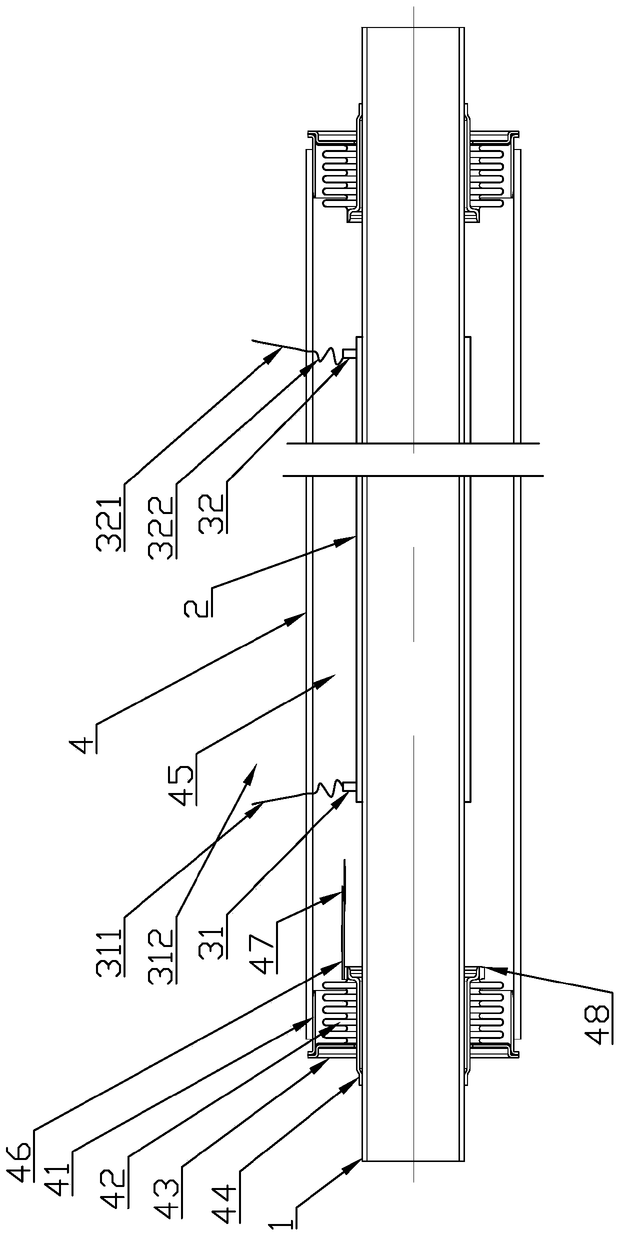
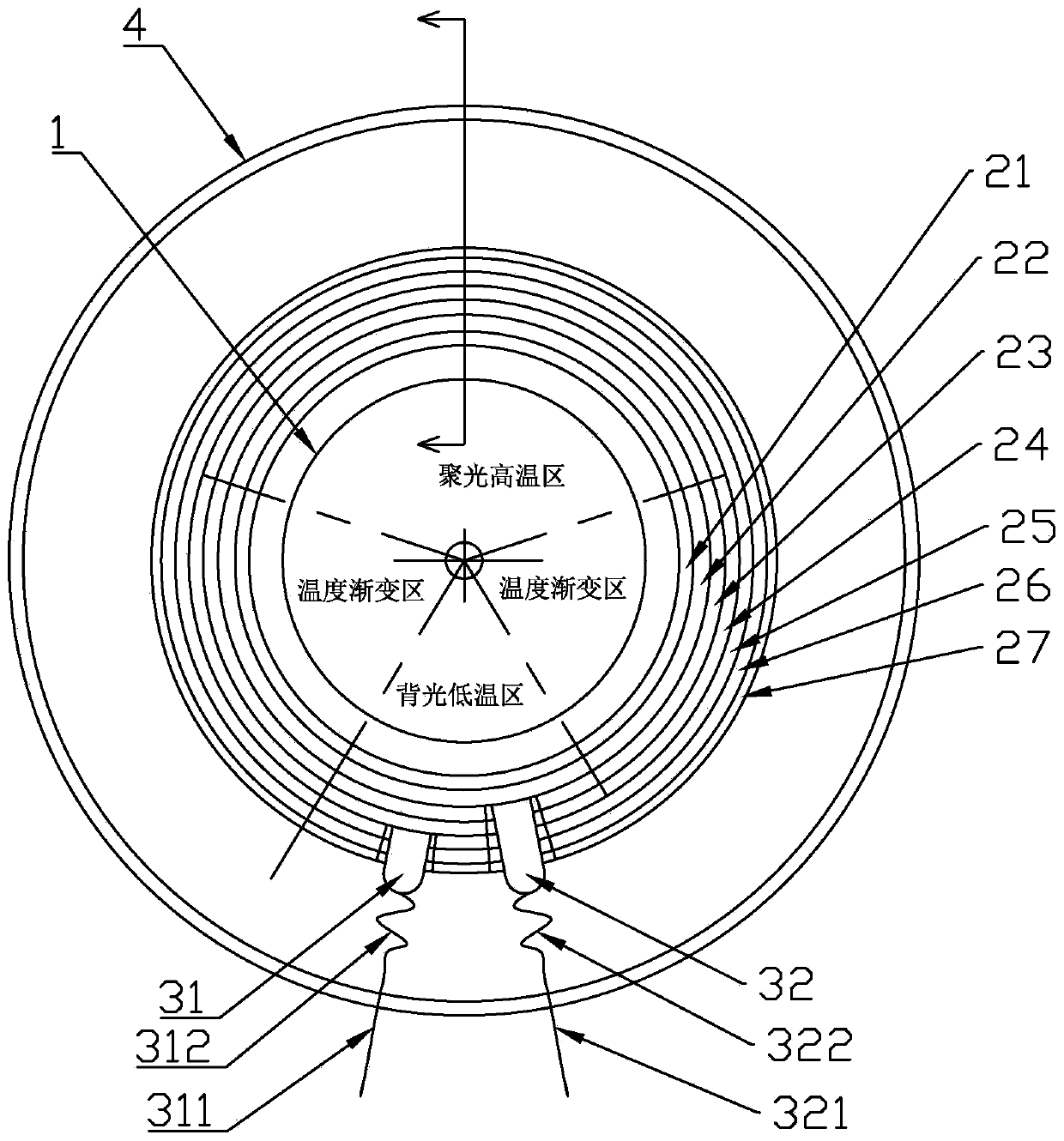
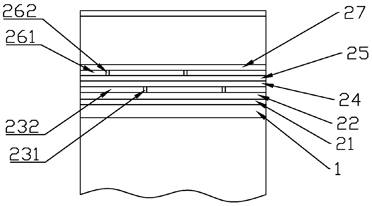
[0037] Such as figure 1 , figure 2 Shown is a longitudinal sectional view and a transverse sectional view of a solar collector tube with a thin-film photovoltaic power generation coupling selective absorption coating structure provided by the present invention. The thermal collector tube includes:

[0038] Steel pipe 1, the fluid to be heated circulates in the pipe, the outer wall is provided with the thin film photovoltaic power generation coupling selective absorption coating structure 2 (the specific structure will be described in detail later), and the coating structure 2 is also connected with the fi...


PUM

PropertyMeasurementUnit
electrical resistanceaaaaaaaaaa
thicknessaaaaaaaaaa
thicknessaaaaaaaaaa

Abstract

The invention provides a solar energy heat collecting tube with a film photovoltaic power generation coupling selective absorption coating. The solar energy heat collecting tube comprises a metal tubeand a hood glass tube which sleeves outside of the metal tube, wherein a film photovoltaic power generation coupling selective absorption coating structure is formed in the outer wall of the metal tube, and extraction electrodes are connected to an inner side electrode coating belt and an outer side electrode coating belt; kovar metal sleeves are respectively in sealing connection with two ends of the hood glass tube, and are in tight connection with the outer wall of the metal tube through corrugated tube assemblies; a vacuum interlayer is formed between each hood glass tube and the metal tube; a bending section is formed by a conducting wire connected with each extraction electrode in the vacuum interlayer; and the tail end of each bending section is led outside the hood glass tube through direct leading or through transition materials. According to the solar energy heat collecting tube disclosed by the invention, a film photovoltaic power generation coupling selective absorption coating production line is perfectly merged to a conventional glass metal sealing solar energy heat collecting tube production line, so that the cost is reduced.

Description

technical field [0001] The invention relates to a coating structure of a solar heat collection tube, in particular to a glass-metal fusion-sealed straight-through solar heat collection tube structure utilizing thin-film photovoltaic power generation coupled with a selective absorption coating. Background technique [0002] Solar energy has the great advantages of being inexhaustible, inexhaustible, clean and environmentally friendly, and has been accepted by the society and developed rapidly. [0003] At present, there are two main ways to utilize solar energy: power generation and heat utilization. Power generation is divided into photovoltaic power generation and solar thermal power generation. Heat utilization mainly converts solar energy into heat energy to provide medium-temperature and low-temperature industrial or civil heat below 250°C. With the development of technology, there is a trend of technology coupling between photovoltaic and photothermal, that is, when s...

Claims


Application Information

Patent Timeline
Patent Type & Authority Applications(China)
IPC IPC(8): F24S10/40F24S10/70F24S70/25F24S70/225
CPCY02E10/44Y02P80/20
Inventor 韩成明薛道荣李峰姜志祥赵露
Owner 河北道荣新能源科技有限公司
Why Eureka
Try Eureka