A Design Method for Tube Spacing of Noncondensable Gas Shell-and-Tube Heat Exchanger

A shell-and-tube heat exchanger and design method technology, applied in the direction of indirect heat exchangers, heat exchanger types, heat exchange equipment, etc., can solve the problems of uneven separation of separation devices, narrow areas, increased flow resistance, etc., to achieve Avoid uneven division, improve the effect of steady flow, and improve the effect of heat exchange

Active Publication Date: 2020-08-18
STATE GRID SHANDONG ENERGY SAVING SERVICE +1
View PDF8 Cites 0 Cited by
  • Summary
  • Abstract
  • Description
  • Claims
  • Application Information

AI Technical Summary

Problems solved by technology

[0005] The inventor also designed a variety of heat exchanger devices to solve the above problems in the previous application, such as multi-tube type, but this kind of device found in operation, because the tubes are tightly combined, so the gap between the three tubes The formed space A is relatively small, because the space A is formed by the convex arc of three pipes, so most of the space A is narrow, which will make it difficult for the fluid to enter and pass through, resulting in a short circuit of the fluid, which affects the heat exchange of the fluid and cannot function good flow stabilization
Simultaneously because the many tubes of above-mentioned structure are combined together, manufacture difficulty
Another example is the 2017102671998 structure. Although this structure solves the fluid short circuit phenomenon, there is a problem that the flow area is greatly reduced, resulting in an increase in flow resistance.
Another example is the annular partition device of 2017103224953. In the annular structure, the partition device adopts a ring structure, which results in uneven separation of the annulus of the partition device in the circumferential direction, and because of the ring structure, the positions of the four included angles of the annulus appear less than Acute angles of 90 degrees, which can cause problems with shorting fluid flow at acute angles less than 90 degrees
[0006] In view of the above problems, the present invention has been improved on the basis of the previous invention, and a new heat exchanger is provided, so as to solve the problem of steady flow and uneven heat exchange in the case of heat exchange with heat exchange tubes

Method used


Image

  • A Design Method for Tube Spacing of Noncondensable Gas Shell-and-Tube Heat Exchanger
  • A Design Method for Tube Spacing of Noncondensable Gas Shell-and-Tube Heat Exchanger
  • A Design Method for Tube Spacing of Noncondensable Gas Shell-and-Tube Heat Exchanger

Examples


Embodiment Construction

[0038] The specific embodiments of the present invention will be described in detail below in conjunction with the accompanying drawings.

[0039] In this article, if there is no special explanation, when it comes to formulas, " / " means division, and "×" and "*" mean multiplication.

[0040] It should be noted that, unless otherwise specified, the two-phase flow mentioned in the present invention is a gas-liquid two-phase flow, and the gas here is an insoluble or poorly soluble gas, that is, the gas will not dissolve in the liquid during the heat exchange process.

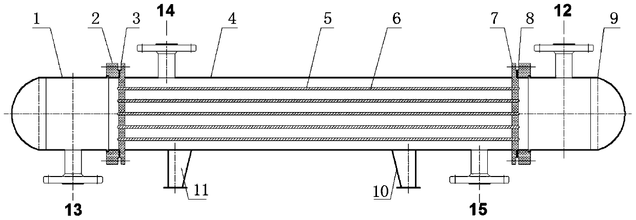
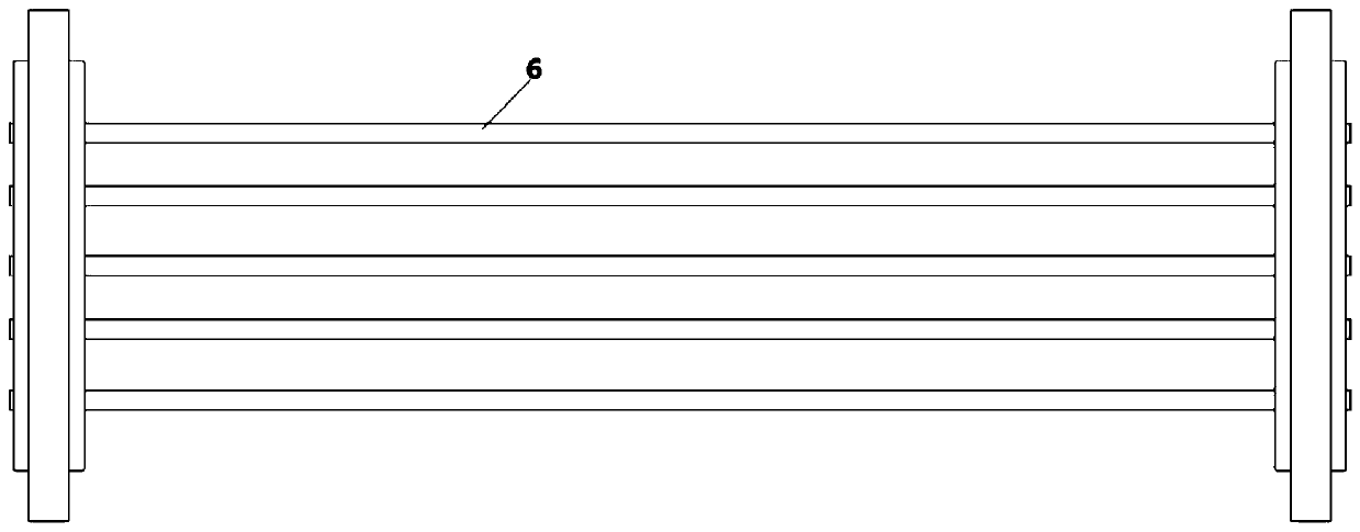
[0041] Such as figure 1 A shell-and-tube heat exchanger is shown, and the shell-and-tube heat exchanger includes a shell 4, a heat exchange tube 6, a tube-side inlet pipe 12, a tube-side outlet pipe 13, a shell-side inlet connecting pipe 14 and a shell The outlet connecting pipe 15; the heat exchange tube bundle composed of a plurality of parallel heat exchange tubes 6 is connected to the front tube sheet 3 and th...


PUM


Abstract

The invention provides a design method for the tube distance of a shell and tube heat exchanger. A division device is arranged in each heat exchange tube and is of a flaky structure. The flaky structures are arranged on the cross sections of the heat exchange tubes. The tube distance of the heat exchange tubes is designed by adopting an optimization method. The design method for the tube distanceof the heat exchanger with the partition devices of new structures is provided, and shock absorption and noise reduction are optimized under the condition of preferentially meeting normal flowing resistance.

Description

technical field [0001] The invention relates to a shell-and-tube heat exchanger, in particular to a two-phase flow heat exchanger containing non-condensable gas. Background technique [0002] Two-phase flow heat exchange containing non-condensable gas widely exists in heat exchange devices, for example, non-condensable gas is mixed in the heat exchange process, or non-condensable gas is produced due to equipment aging during fluid transportation, and natural gas, for example Condensation of mixed media with different boiling points, air separation, mixed refrigerant refrigeration, petroleum or waste plastic cracking, production The main technological process of industries such as material gas production. [0003] The existence of the gas phase in the heat exchange process of the fluid containing non-condensable gas will lead to low heat exchange efficiency, worse heat exchange, unstable fluid flow process, and water hammer phenomenon. When the gas-liquid phase of the two-p...

Claims


Application Information

Patent Timeline
Patent Type & Authority Patents(China)
IPC IPC(8): F28D7/16F28F13/00
Inventor 马俊迪张爱群杨伟进朱国梁孙秀青张宏涛陈晓东靳印涵张冠敏张毅邱燕王效嘉江程李言伟
Owner STATE GRID SHANDONG ENERGY SAVING SERVICE
Why Eureka
Try Eureka