Spherical joint movement sensor

A technology for moving sensors and joints, applied in instruments, measuring devices, electrical devices, etc., can solve the problems of poor system stability, difficult to guarantee accuracy, and high system cost.

Pending Publication Date: 2019-06-07
ZHONGBEI UNIV
View PDF9 Cites 3 Cited by
  • Summary
  • Abstract
  • Description
  • Claims
  • Application Information

AI Technical Summary

Problems solved by technology

The main reason is that the existing achievements have defects such as ...

Method used


Image

  • Spherical joint movement sensor
  • Spherical joint movement sensor
  • Spherical joint movement sensor

Examples


Embodiment Construction

[0025] The present invention will be further described below in conjunction with the accompanying drawings.

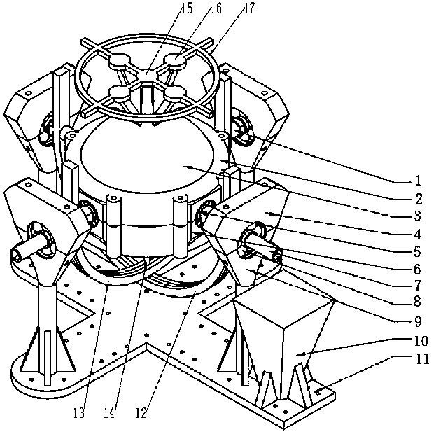
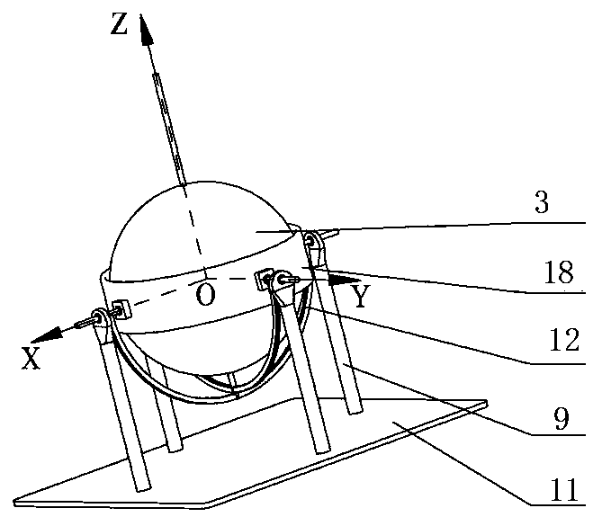
[0026] like figure 1 , figure 2 As shown, a ball joint movement sensor of the present invention includes a sphere 3, a bracket 18, an outer slide rail 12, an inner slide rail 13 and a single-axis angle encoder. The equator of the sphere 3 is surrounded by the bracket 18, and the sphere 3 It forms a rotatable fit with the bracket 18. The top of the ball 3 is provided with an action receiving part 15, and the bottom of the ball 3 is provided with a decoupling slider 14. Both the outer slide rail 12 and the inner slide rail 13 are provided with a slit in the middle. Semi-circular arc track, the two sides of the outer slide rail 12 and the inner slide rail 13 are hinged on the bracket 18 through the coupling device, and the decoupling slider 14 passes through the slit of the inner slide rail 13 and connects with the slit of the outer slide rail 12 Hinged, the outer end ...


PUM


Abstract

The invention relates to a spherical joint movement sensor and belongs to the field of spatial rotation angle measurement technologies. The invention aims to provide a special measurement system for measuring the rotation angle of a spherical joint. According to the technical schemes of the invention, the spherical joint movement sensor includes a sphere, a supporting bracket, an outer slide rail,an inner slide rail and single-axis angle encoders; the equator portion of the sphere is surrounded by the supporting bracket; the sphere is in rotatable fit with the supporting bracket; the top endof the sphere is provided with an action receiving portion; the bottom end of the sphere is provided with a decoupling slider; each of the outer slide rail and the inner slide rail is a semi-circulararc rail with a slit formed in the middle; two sides of each of the outer slide rail and the inner slide rail are hinged to the supporting bracket through coupling devices; the decoupling slider passes through the slit of the inner slide rail and is hinged to the slit of the outer slide rail; and the outer ends of the coupling devices are connected with the single-axis angular encoders.

Description

technical field [0001] The invention relates to a ball joint movement sensor, which belongs to the technical field of space rotation angle measurement. Background technique [0002] In the field of machinery manufacturing, the pursuit of high precision and high quality is the common goal of the entire industry, but the resulting disadvantages such as complex structure, high processing costs, and reduced output are always difficult to eliminate. If processing is carried out in one dimension, high precision is relatively easy to achieve, but now the product structure required is becoming more and more complex, and often needs to be processed on parallel or hybrid machine tools (Su Yong. Talking about the open CNC system of parallel robots Construction [J]. Science and Technology Information, 2015, (33): 18-19.). Spherical joints are widely used in these devices, and in parallel mechanisms, the ball joint gap is a key error factor, which affects and restricts the application o...

Claims


Application Information

Patent Timeline
IPC IPC(8): G01B7/30
Inventor 郭彦青刘璐范晓晨俞恒杰
Owner ZHONGBEI UNIV
Why Eureka
Try Eureka