Non-contact rail wear detector, and wear detection method

A rail wear and non-contact technology, applied to instruments, measuring devices, optical devices, etc., can solve problems such as buckle wear, inaccurate positioning, and difficulty in moving instruments, so as to facilitate installation and movement and improve storability , the effect of improving the detection efficiency

Inactive Publication Date: 2019-06-07
SOUTHWEST JIAOTONG UNIV
View PDF6 Cites 1 Cited by
  • Summary
  • Abstract
  • Description
  • Claims
  • Application Information

AI Technical Summary

Problems solved by technology

[0004] The rail side vertical grinding instrument is the most widely used contact measurement wear method. The instrument is mainly composed of two vernier calipers and a rail head buckle. At present, both digital display and mechanical vernier calipers are used. The main problems are: The caliper probe is severely worn, the mechanical reading error is large, and the vernier is easy to fall off during the measurement process. The vernier caliper needs to be reset to zero using a standard rail module, etc., resulting in low detection efficiency and detection accuracy; the buckle uses a powerful magnet, making the measurement The instrument is closely attached to the rail, and its disadvantages are: due to the strong magnetic force, it is extremely difficult to install the instrument, and it is easy to collide between the caliper and the rail, which will damage the instrument. Difficult to move, and lead to severe wear of the buckle, a large amount of iron chips are absorbed between the buckle and the rail, resulting in inaccurate positioning, low detection efficiency and accuracy
[0005] The rail side pendant grinder is a contact mechanical type. In the process of use, two people are generally required to work at the same time. One person operates the instrument and the other records the data. The data cannot be saved automatically, the detection efficiency is low and it is not convenient for digital management; and the operator It takes a long time to bend over to read the value of the vernier caliper, which is easy to cause physical damage to the measuring personnel, and the work intensity is high

Method used


Image

  • Non-contact rail wear detector, and wear detection method
  • Non-contact rail wear detector, and wear detection method
  • Non-contact rail wear detector, and wear detection method

Examples


Embodiment Construction

[0030] The following describes the implementation of the present invention through specific specific examples. Those skilled in the art can easily understand other advantages and effects of the present invention from the content disclosed in this specification. The present invention can also be implemented or applied through other different specific embodiments, and various details in this specification can also be modified or changed based on different viewpoints and applications without departing from the spirit of the present invention.

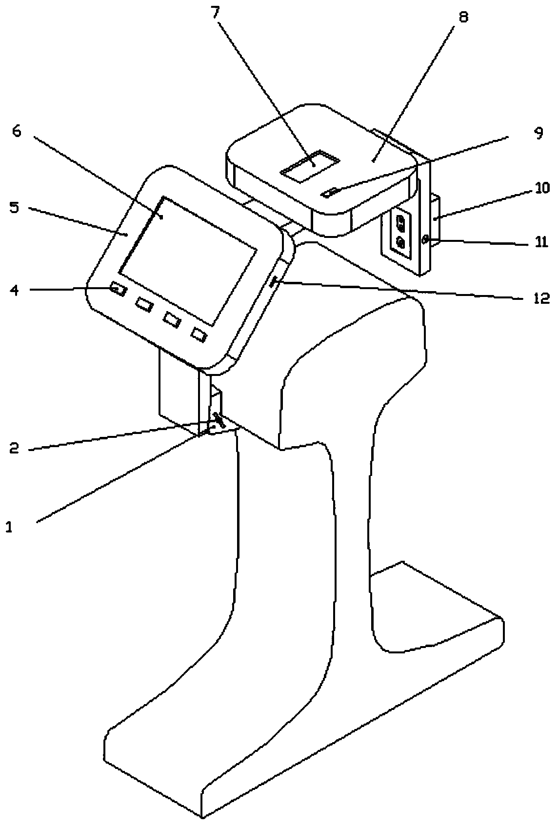
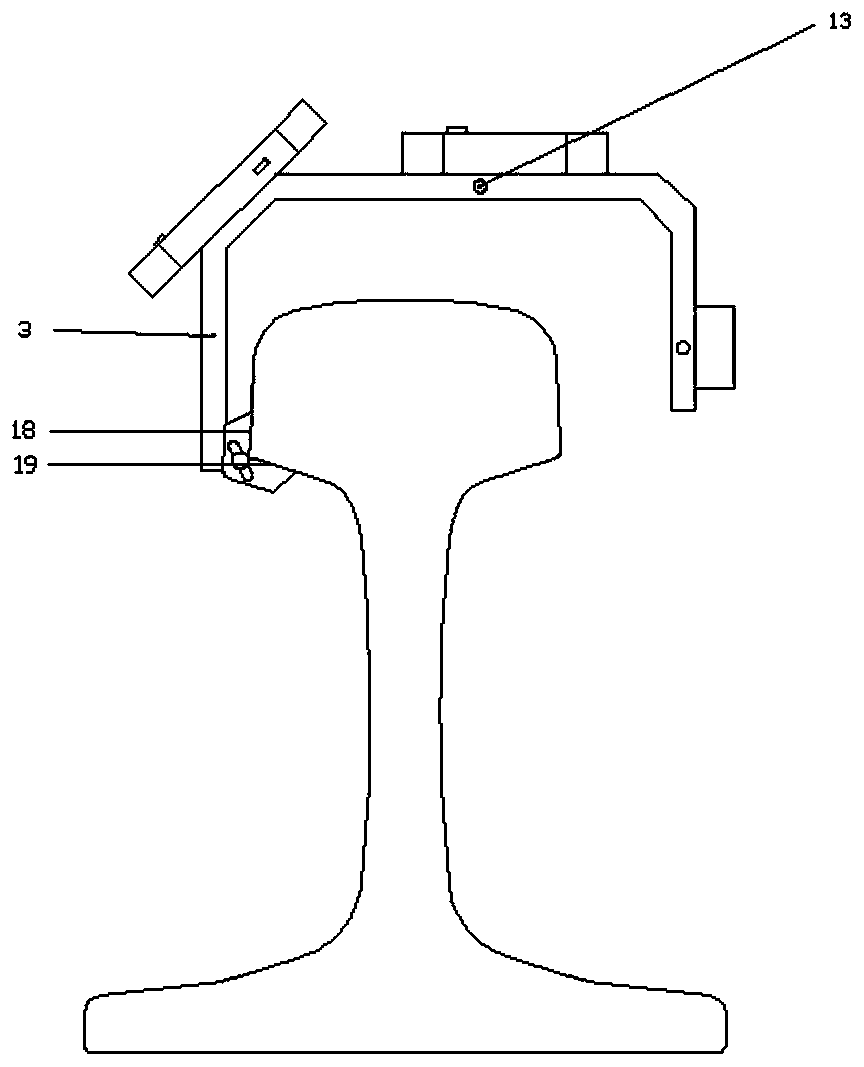
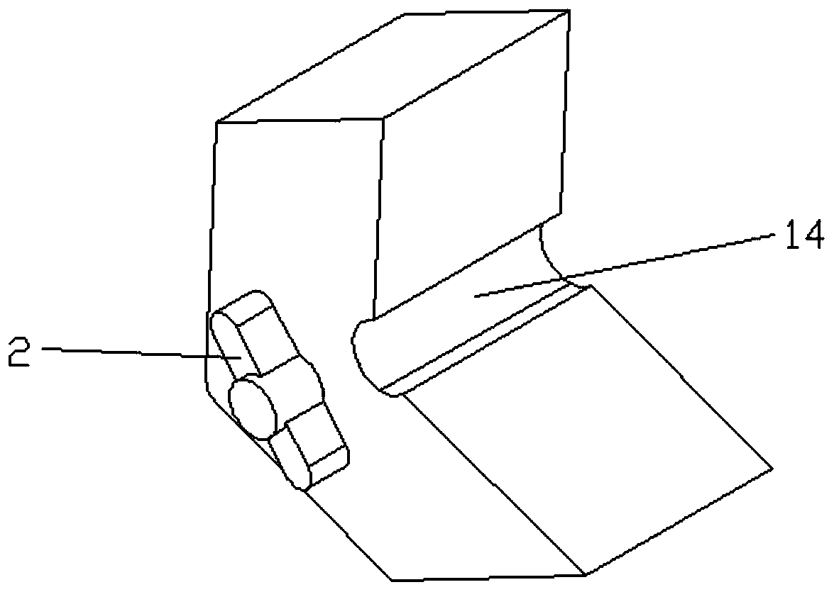
[0031] A non-contact rail wear detector includes a carrying frame 3, a detection module on the carrying frame, and a positioning module 1, and also includes a data processing storage module, a data display module 5, and a battery module 8.

[0032] The detection module includes two laser displacement sensors: the first sensor 7 and the second sensor 10. The first sensor is located above the rail and is aligned with the rail head vertical grindin...


PUM


Abstract

The invention provides a non-contact rail wear detector, and a detection method. The detector comprises a carrying frame, a detection module, and a positioning module, wherein the detection module comprises a first sensor and a second sensor; the first sensor is aligned with a rail head vertical wear measuring point, and the second sensor is aligned with a rail head side wear measuring point; thepositioning module adopts a device with a controllable magnetic force for positioning, and comprises cast irons, a non-magnetizer, a cylindrical cavity, an electrical soft iron, and a permanent magnet; and when the permanent magnet rotates to a position where the permanent magnet is perpendicular to the non-magnetizer, magnetic lines penetrate the sides and the lower jaw of a rail head and then return to the permanent magnet to form a closed loop, so that the cast irons produce absorption effects to firmly absorb the sides and the lower jaw of the rail head. The detector adopting the design has the advantages that the positioning device has the property of the controllable magnetic force, so that the instrument can be conveniently installed and moved, and the detection efficiency can be improved; and laser displacement sensors are used for measuring, so that the measured data precision and the measuring efficiency are high.

Description

Technical field [0001] The invention belongs to the present invention and relates to a detection instrument, in particular to a non-contact rail wear detector and a method for non-contact wear detection using the detector. Background technique [0002] With the rapid development of science and technology in my country, China's high-speed rail is developing rapidly. As the speed of railways continues to increase, it is not only necessary to ensure the comfort of passengers, but also to ensure the safety of trains. The detection of rail wear is particularly important. The friction between wheels and rails is the main form of rail loss. Therefore, strengthening the wear detection of steel rails and processing them in time according to the detection results are effective ways to improve the safety of railway transportation and the comfort of passengers. [0003] At present, the testing parameters of rail wear in my country mainly include vertical wear and side wear. The testing freque...

Claims


Application Information

Patent Timeline
Patent Type & Authority Applications(China)
IPC IPC(8): G01B11/14
Inventor 王培俊郑小江康凯宁陈亚东李文涛付文龙
Owner SOUTHWEST JIAOTONG UNIV
Why Eureka
Try Eureka