
Method for generating gas flow field grid model under complex launching technical conditions

A technical condition and grid model technology, which is applied in the field of gas flow field grid model generation, can solve the problems of large grid size, long calculation process, and huge computing resources, so as to save computing resources and control the number of grids , the effect of improving computational efficiency

Active Publication Date: 2019-06-07
BEIJING INST OF SPACE LAUNCH TECH +1
View PDF4 Cites 0 Cited by
  • Summary
  • Abstract
  • Description
  • Claims
  • Application Information

AI Technical Summary

Problems solved by technology

[0003] In order to ensure safe launch, large-tonnage rockets are often equipped with a lot of auxiliary equipment to improve safety measures, such as deflectors, check arms, swing rods, heat shields, locks tightening mechanisms, etc., thereby increasing the complexity of the system, and at the same time directly causing the complexity of gas flow propulsion and turbulence during the take-off process of large-tonnage rockets. Taking road maneuvering launch as an example, the gas flow ejected by the rocket engine will bear the recoil of the flow guide device function, the turbulence effect of the launch pad containment arm (or support arm) and the outrigger, frame and other special-shaped structures, so the flow form of the gas flow is extremely complicated
[0004]In order to ensure the accuracy of the calculation results, the real configuration of each structural member in the flow field is usually preserved, and the grid scale on the surface of the structural member is controlled, which will bring As a result of the large amount of grids, the calculation resources are very large, and the calculation process is also very long

Method used


Image

  • Method for generating gas flow field grid model under complex launching technical conditions
  • Method for generating gas flow field grid model under complex launching technical conditions
  • Method for generating gas flow field grid model under complex launching technical conditions

Examples


Embodiment Construction

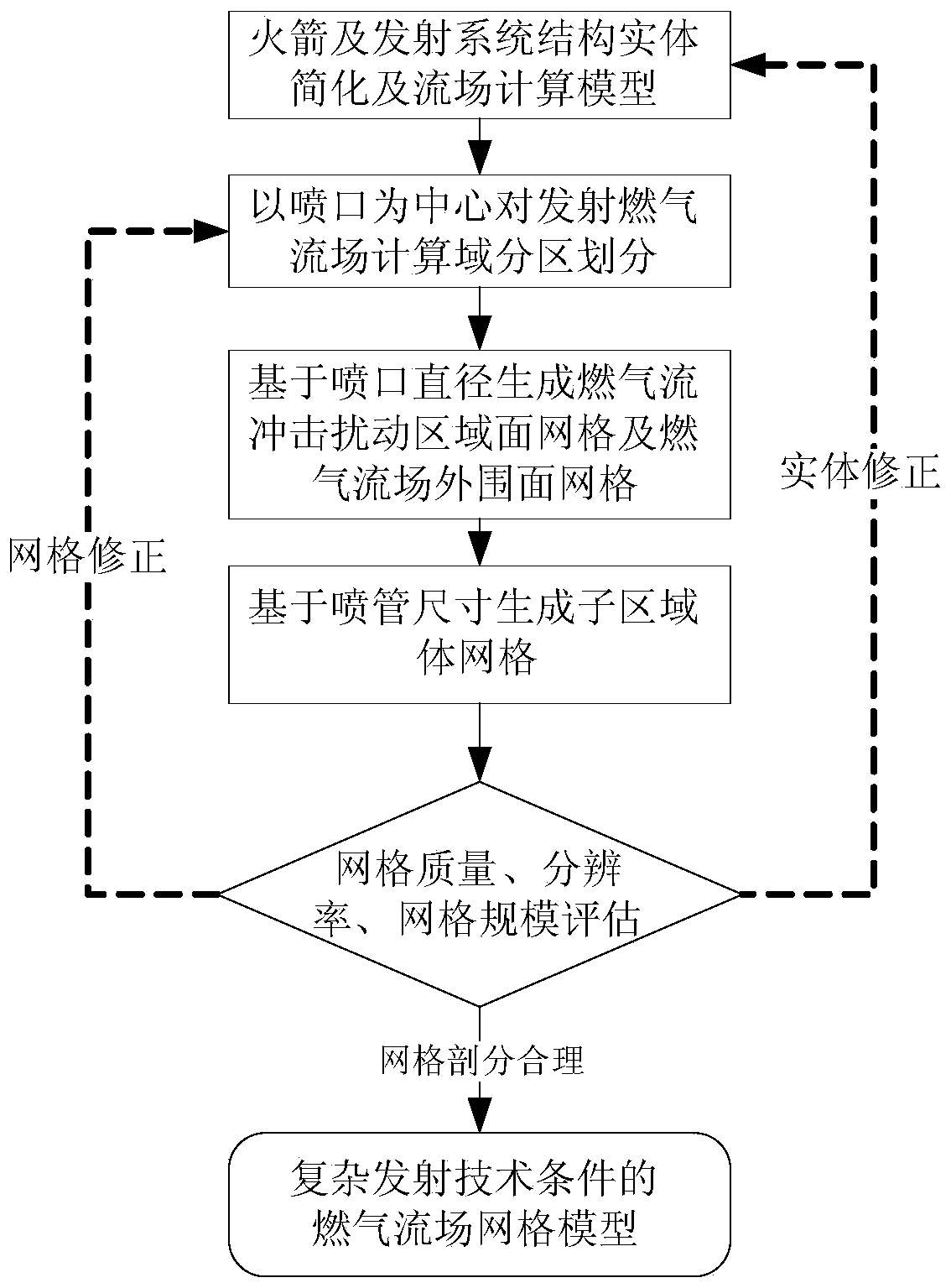
[0049] like figure 1 Shown, concrete steps of the present invention are as follows:

[0050] Step 1: Simplify the physical structure model of the rocket and launch system to obtain the flow field calculation model;

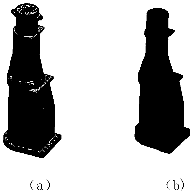
[0051] The simplification of the solid structure model of the rocket and launch system includes the following aspects: 1. Retain the structural surface contour of the gas flow positive impact range to ensure the accuracy of the calculation model; 2. Fill the small gaps on the structural surface; 3. In the leeward area, the outer contours of protrusions or depressions that have little influence on the flow field are smoothed; 4. Small-scale structural protrusions or depressions in the windward area are smoothed.

[0052] The schematic diagram of the simplified processing of the resulting model is as follows: figure 2 As shown, where (a) is the structure before simplification, and (b) is the structure after simplification. Import the simplified solid model into ...


PUM


Abstract

The invention discloses a method for generating a gas flow field grid model under complex launching technical conditions, which comprises the following steps of: simplifying a rocket and launching system entity structure model to obtain a flow field calculation model; taking the center of a to-be-launched state nozzle of the rocket as a reference center, and taking the diameter of the nozzle as areference scale to carry out partition division on a launched gas flow field calculation domain; continuously generating a gas flow impact disturbance region surface grid and a gas flow field peripheral surface grid by taking the nozzle diameter as a reference scale, and generating a sub-region body grid by taking the nozzle diameter as the reference scale; and finally, evaluating the quality, theresolution and the scale of the grid. According to the method, under the condition of ensuring enough grid resolution, the quality and quantity of the grids are effectively controlled, computing resources are saved, and the computing efficiency is improved.

Description

technical field [0001] The invention relates to a method for generating a grid model of a gas flow field under complex emission technical conditions, and belongs to the field of gas flow field simulation. Background technique [0002] The gas flow field simulation is the first link in the demonstration of the launch technical scheme, which determines the rocket take-off attitude, the overall design of the launch system, especially the design of the aerodynamic layout, and is also the basis for the thermal protection of the launch system (or facility). The first step in field simulation is to develop a suitable discrete model of computational grid cells (grid model for short). [0003] In order to ensure safe launch, large-tonnage rockets are often equipped with a lot of auxiliary equipment to improve safety measures, such as deflectors, containment arms, swing rods, heat shields, locking mechanisms, etc., thereby increasing the complexity of the system and directly causing l...

Claims


Application Information

Patent Timeline
IPC IPC(8): G06F17/50G06T17/00
CPCY02T90/00
Inventor 陈劲松王明华杜小坤吴新跃贾延奎曾玲芳王帅
Owner BEIJING INST OF SPACE LAUNCH TECH
Learn More