Temporary grounding clamp of transmission line tower

A temporary grounding and transmission line technology, applied in the direction of cable installation, contact parts, electrical components, etc., can solve the problems of grounding resistance not meeting the requirements, inconvenient to find the main grounding network, etc., to avoid line damage, ensure firmness, The effect of improving work efficiency

Active Publication Date: 2019-06-07
国网山东省电力公司建设公司 +2
View PDF6 Cites 0 Cited by
  • Summary
  • Abstract
  • Description
  • Claims
  • Application Information

AI Technical Summary

Problems solved by technology

[0003] At present, most of the temporary grounding devices are plug-in grounding devices of galvanized grounding rods. Sometimes the grounding resistance does not meet the requirements due to improper insertion, and it is inconvenient to find the main grounding network when the formal grounding down-conductor is constructed later. Therefore, it is necessary to have a Safer temporary ground connection

Method used


Image

  • Temporary grounding clamp of transmission line tower
  • Temporary grounding clamp of transmission line tower
  • Temporary grounding clamp of transmission line tower

Examples


Embodiment 1

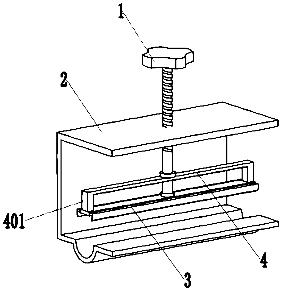
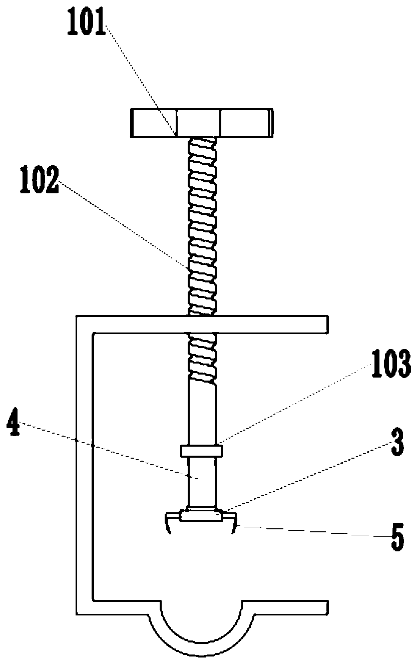
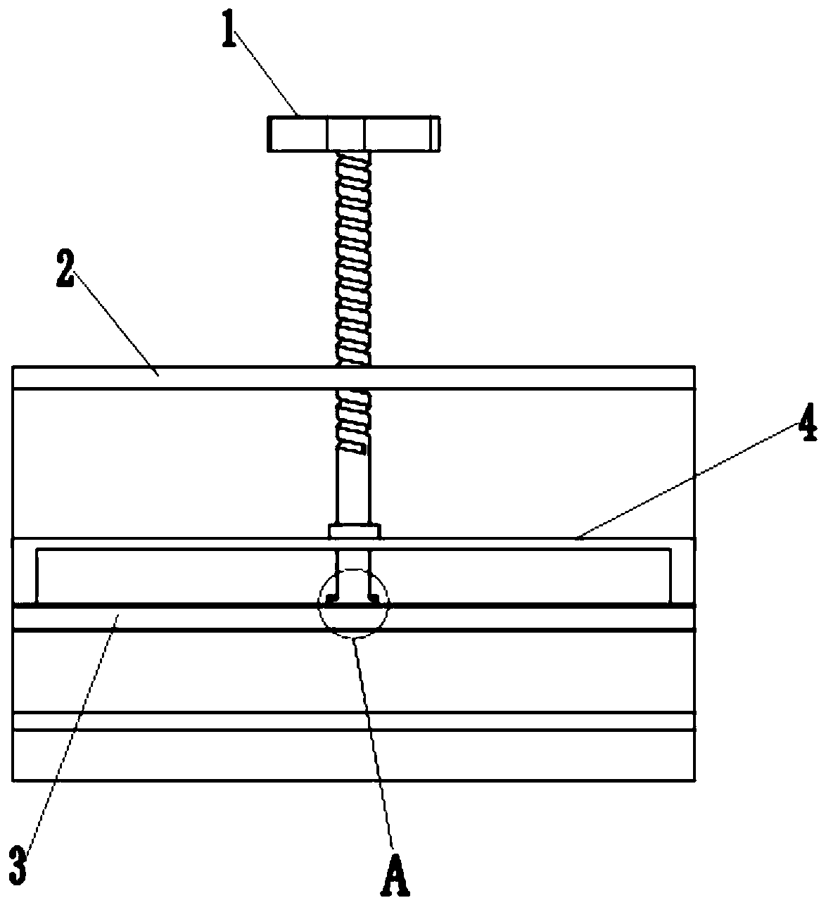
[0034] like Figure 1-3 As shown, a temporary grounding fixture for a power transmission line tower includes an adjusting rod 1, a supporting shell 2, and a pressing rod 3, such as Figure 5 As shown, the support shell 2 includes a support plate 201, a connecting plate 203, and a pressure plate 205. The support plate 201 and the pressure plate 205 are arranged in parallel, and the connection plate 203 connection, the upper end of the crimping plate 205 is provided with a fixing groove 204 with openings at both ends, the fixing groove 204 is a semi-circular arc structure, the length of the fixing groove 204 and the wire pressing plate 205 are the same as 150mm, and the adjusting rod 1 is provided with an external thread 102 on the side wall, one end of the adjustment rod 1 is rotationally connected with the middle part of the pressure rod 3, the support plate 201 is provided with a threaded hole 202, the adjustment rod 1 is matched with the threaded hole 202, and the pressure r...

Embodiment 2

[0041] In order to make it more convenient to fix the wire during use, a guide rod 7 is added to replace the manual fixing of the pressure rod 3, and the position of the pressure rod can be limited when the adjustment rod is rotated to ensure that the pressure rod can only move up and down to prevent the pressure rod from rotating. Increase the convenience of use.

[0042] like Figure 8 As shown, both sides of the threaded hole 202 are provided with guide holes 206, the guide holes 206 are arranged near the end of the support plate 201, and both sides of the upper end of the reinforcing rod 4 are provided with guide rods 7, the The guide rod 7 cooperates with the guide hole 206 .

[0043] like Figure 9 As shown, the guide rod 7 is covered with a second spring 8 , the upper end of the second spring 8 is connected to the lower end surface of the support plate 201 , and the lower end of the second spring 8 is connected to the upper end surface of the reinforcing rod 4 .

[0...


PUM


Abstract

The present invention discloses a temporary grounding clamp of a transmission line tower. The temporary grounding clamp comprises a regulation rod, a support housing and a pressing rod. The support housing comprises a support plate, a connection plate and a line pressing plate, the support plate is connected with the line pressing plate through the connection plate, the upper end of the line pressing plate is provided with a line fixing groove with two opening ends, the side wall of the regulation rod is provided with external threads, one end of the regulation rod is rotationally connected with the middle portion of the pressing rod, the support plate is provided with a threaded hole, the regulation rod is matched with the threaded hole, the pressing rod is arranged between the support plate and the line pressing plate, and the two sides of the pressing rod are both provided with line collection elastic plates. The temporary grounding clamp can meet the temporary grounding depth of the transmission line and the tight connection of the temporary grounding line and wires and cables of a main grounding grid, can meet the requirement of a grounding resistor, performs bolted connectionwith grounding holes at the tower body when the tower is assembled, and can be taken as a mark line to conveniently find the grounding grid in the formal grounding construction so as to save the latework and improve the work efficiency.

Description

technical field [0001] The invention relates to the technical field of cable clamps, in particular to a temporary grounding clamp for power transmission line towers. Background technique [0002] The grounding device of the transmission line tower is an important part of the transmission line project and plays an important role in the safe operation of the power grid. At present, the formal grounding down conductors of transmission line projects are mostly installed after the protective cap is completed. One is to meet the installation requirements of the standard process, and the other is to facilitate the control of its length during installation. For a period of time, grounding is still required according to the specification requirements, so a temporary grounding method is required. [0003] At present, most of the temporary grounding devices are plug-in grounding devices of galvanized grounding rods. Sometimes the grounding resistance does not meet the requirements due...

Claims


Application Information

Patent Timeline
Patent Type & Authority Applications(China)
IPC IPC(8): H01R4/66H01R4/38H01R4/42H01R13/15H02G7/00
Inventor 颜廷雪王延鹏顿家宝唐海滨刘红涛韩非郭峰商志宙汪先涛邵霞
Owner 国网山东省电力公司建设公司
Why Eureka
Try Eureka