System and method for mounting a robotic arm in a surgical robotic system

A technology for robotic arms and installation equipment, applied in surgical navigation systems, robots, surgical robots, etc., can solve the problem of occupying space in the surgical area

Active Publication Date: 2019-06-07
MOBIUS IMAGING
View PDF14 Cites 1 Cited by
  • Summary
  • Abstract
  • Description
  • Claims
  • Application Information

AI Technical Summary

Problems solved by technology

Surgical robotic systems are typically large devices that approach the patient from the side and may occupy a relatively large amount of space in the surgical field

Method used


Image

  • System and method for mounting a robotic arm in a surgical robotic system
  • System and method for mounting a robotic arm in a surgical robotic system
  • System and method for mounting a robotic arm in a surgical robotic system

Examples


Embodiment Construction

[0028] Various embodiments will be described in detail with reference to the accompanying drawings. Wherever possible, the same reference numbers will be used throughout the drawings to refer to the same or like parts. References made to particular examples and implementations are for illustrative purposes, and are not intended to limit the scope of the invention or the claims.

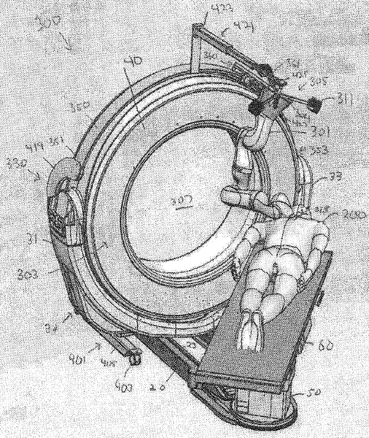
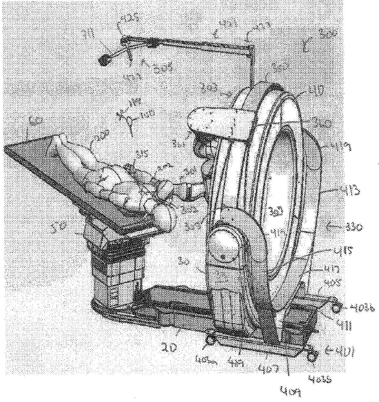
[0029] Figures 1A to 1D A system 300 for performing robot-assisted image-guided surgery is illustrated in accordance with various embodiments. Figure 1A is a front perspective view of the system 300, and Figure 1B is a rear perspective view of system 300 . Figure 1C is a top view of the system 300, and Figure 1D is a front elevation view of system 300 . In this embodiment system 300 includes a robotic arm 301 , an imaging device 303 and a motion tracking system 305 . The robotic arm 301 may comprise a multi-articulated arm comprising a plurality of links connected by articulations with actu...


PUM


Abstract

Systems and methods for mounting a robotic arm for use in robotic-assisted surgery, including a mobile shuttle that includes a support member for mounting the robotic arm that extends at least partially over a gantry of an imaging device. Further embodiments include a mounting apparatus for mounting a robotic arm to a base or support column of an imaging device, to a patient table, to a floor or ceiling of a room, or to a cart that extends over the top surface of the patient table.

Description

[0001] related application [0002] This application asserts U.S. Provisional Application No. 62 / 395,443, filed September 16, 2016, U.S. Provisional Application No. 62 / 426,491, filed November 26, 2016, and 62 / 491,645, filed April 28, 2017 Priority to US provisional applications, all of which are incorporated herein by reference in their entirety. Background technique [0003] Robot-assisted surgical procedures have attracted increasing interest in recent years. Robot-assisted surgery involving robot-assisted minimally invasive surgical procedures may be faster, safer, and require less recovery time than conventional open surgery. Surgical robotic systems are typically large devices that approach the patient from the side and may occupy a relatively large amount of space in the surgical field. There is a continuing need to improve the usability and effectiveness of surgical robotic systems. Contents of the invention [0004] Various embodiments include systems and methods...

Claims


Application Information

Patent Timeline
Patent Type & Authority Applications(China)
IPC IPC(8): A61B34/00A61B34/30A61B90/00A61B17/00A61B34/20
CPCA61B34/30A61B34/20A61B34/00A61B90/37A61B2090/3762A61B2034/2055A61B90/50A61B6/0407A61B2090/571A61B6/4405A61B6/4458Y10S901/50A61B5/6835B25J5/007B25J5/04B25J9/0018B25J9/0027B25J9/0096B25J9/1697
Inventor P·西布林E·格雷格森R·斯坦顿E·戴利G·罗
Owner MOBIUS IMAGING
Why Eureka
Try Eureka