Eureka AIR delivers breakthrough ideas for toughest innovation challenges, trusted by R&D personnel around the world.

Workpiece collection point unit and method for assisting the machining of workpieces

A collection point, workpiece technology, applied in the direction of metal processing, manufacturing tools, transportation and packaging, etc., can solve the problems of hindering the process, wrong storage of parts, etc.

Active Publication Date: 2019-06-07
TRUMPF WERKZEUGMASCHINEN GMBH & CO KG
View PDF17 Cites 2 Cited by
  • Summary
  • Abstract
  • Description
  • Claims
  • Application Information

AI Technical Summary

Problems solved by technology

Subsequent processes are adversely hampered if parts are stored incorrectly

Method used


Image

  • Workpiece collection point unit and method for assisting the machining of workpieces
  • Workpiece collection point unit and method for assisting the machining of workpieces
  • Workpiece collection point unit and method for assisting the machining of workpieces

Examples


Embodiment Construction

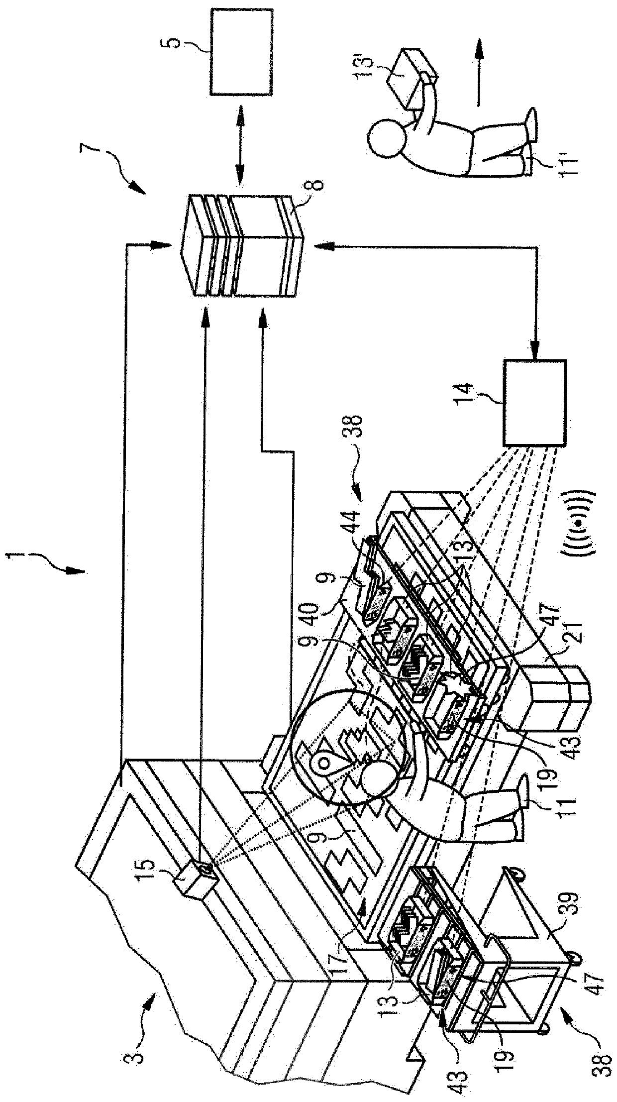
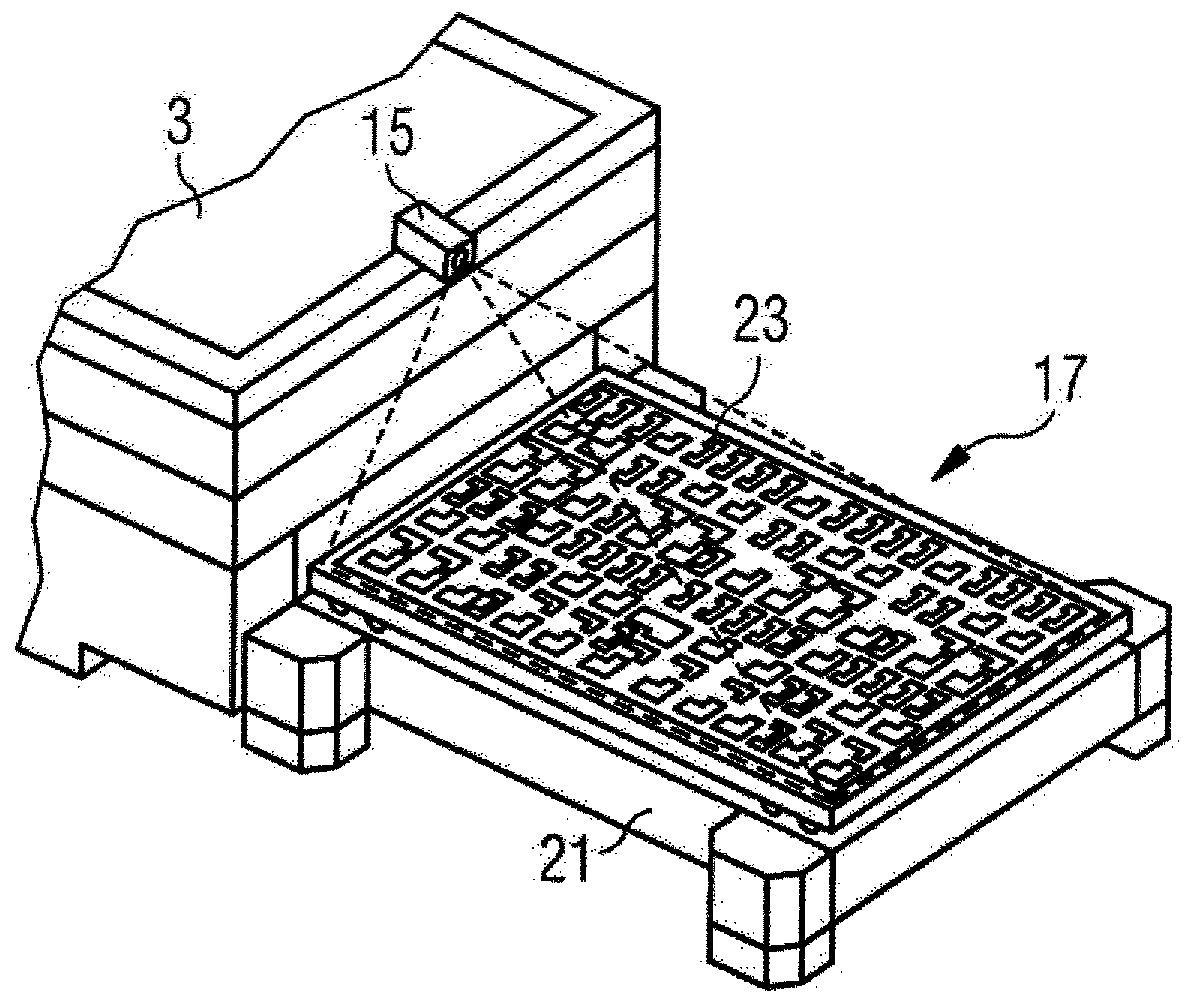
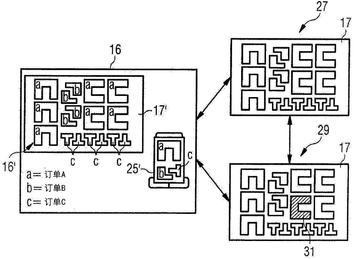
[0064] The aspects described here are based in part on the recognition that in laser cutting or stamping platform machines, the presence of an accurate cutting plan combined with imaging sensing of the sorting table on which the resulting cuts are placed can be used to assist in sorting. selected process and used to obtain information suitable for other process flows.

[0065] The approach described here relates in particular to a flat-plate plant which produces workpieces for subsequent processing steps from so-called sheet metal (starting metal sheets with a predetermined thickness and predetermined area dimensions) by means of stamping or cutting. In particular, the workpiece can be converted into a freely selectable flat shape in the case of flat-bed machines by the processing of sheet metal which is made very flexible by the use of a laser. Subsequent bending and welding processes produce three-dimensional products. In such laser cutting or stamping flatbed machines, a m...


PUM


Abstract

A workpiece collection point unit (13) for a machine tool, in particular for a flatbed machine tool, such as a flatbed laser-cutting or die-punching machine tool (3), has a depositing area (41) for workpieces (9) produced by the machine tool as part of a machining plan (16), a display unit (43) for displaying to a user (11) workpiece information about the workpieces (9) which have been deposited in the depositing region (41) and are intended for further processing, and a signaling device (47) for emitting an identification signal which indicates to a user (11) the position of the selected workpiece collection point unit (13) for depositing the workpiece (9) intended for further processing. The workpiece collection point unit (13) can be used, for example, with a method for assisting a sequence of machining steps carried out to machine workpieces (9).

Description

technical field [0001] The invention relates to a method for assisting a sequence of machining steps for machining a workpiece, in particular by integrating an information flow into the sequence of machining steps. Furthermore, the invention relates to a correspondingly configured workpiece collection point unit. Background technique [0002] When sorting parts on a machine tool, especially laser cut or stamped workpieces, especially sheet metal, the operator usually visually compares each individual cut part with the order diagram of the corresponding part. This mostly paper-based sorting requires individual locating of specific finished parts and their correspondence to the correct order, so that corresponding further processing can start. In this case, the cut or stamped sheet metal parts are often made available in composite form after the machining process to subsequent corresponding production steps. Visual comparisons are labor-intensive and error-prone, especially ...

Claims


Application Information

Patent Timeline
Patent Type & Authority Applications(China)
IPC IPC(8): B25J9/16B07C7/00B65G1/137G05B19/418
CPCB25J9/1697G05B19/4183G05B2219/31372G05B2219/32037G05B2219/45047B07C7/005B26D5/007B65G1/1378Y02P90/02G06V40/28G05B2219/31304B23Q7/12G05B19/401G05B19/40935G05B2219/32014G05B2219/36167
Inventor M·基弗J·奥特纳德E·瓦尔K·魏斯B·施瓦茨P·施普林格
Owner TRUMPF WERKZEUGMASCHINEN GMBH & CO KG
Why Eureka
Eureka Blog
Learn More