Fingerprint identification device and electronic device

A fingerprint recognition and fingerprint sensor technology, applied in the information field, can solve the problems of the imaging effect of optical fingerprint sensor and other problems

Active Publication Date: 2019-06-07
SHENZHEN GOODIX TECH CO LTD
View PDF6 Cites 51 Cited by
  • Summary
  • Abstract
  • Description
  • Claims
  • Application Information

AI Technical Summary

Problems solved by technology

In order to meet the thinning requirements of terminal equipment, the thickness of the optical path guiding structure can be reduced to reduce

Method used


Image

  • Fingerprint identification device and electronic device
  • Fingerprint identification device and electronic device
  • Fingerprint identification device and electronic device

Examples


Example Embodiment

[0031] The technical solutions in the embodiments of the present application will be described below in conjunction with the accompanying drawings.

[0032] It should be understood that the embodiments of this application can be applied to optical fingerprint systems, including but not limited to optical fingerprint identification systems and medical diagnostic products based on optical fingerprint imaging. The embodiments of this application only take optical fingerprint systems as an example for illustration, but should not be used for this The embodiments of the application constitute any limitation, and the embodiments of the application are also applicable to other systems using optical imaging technology.

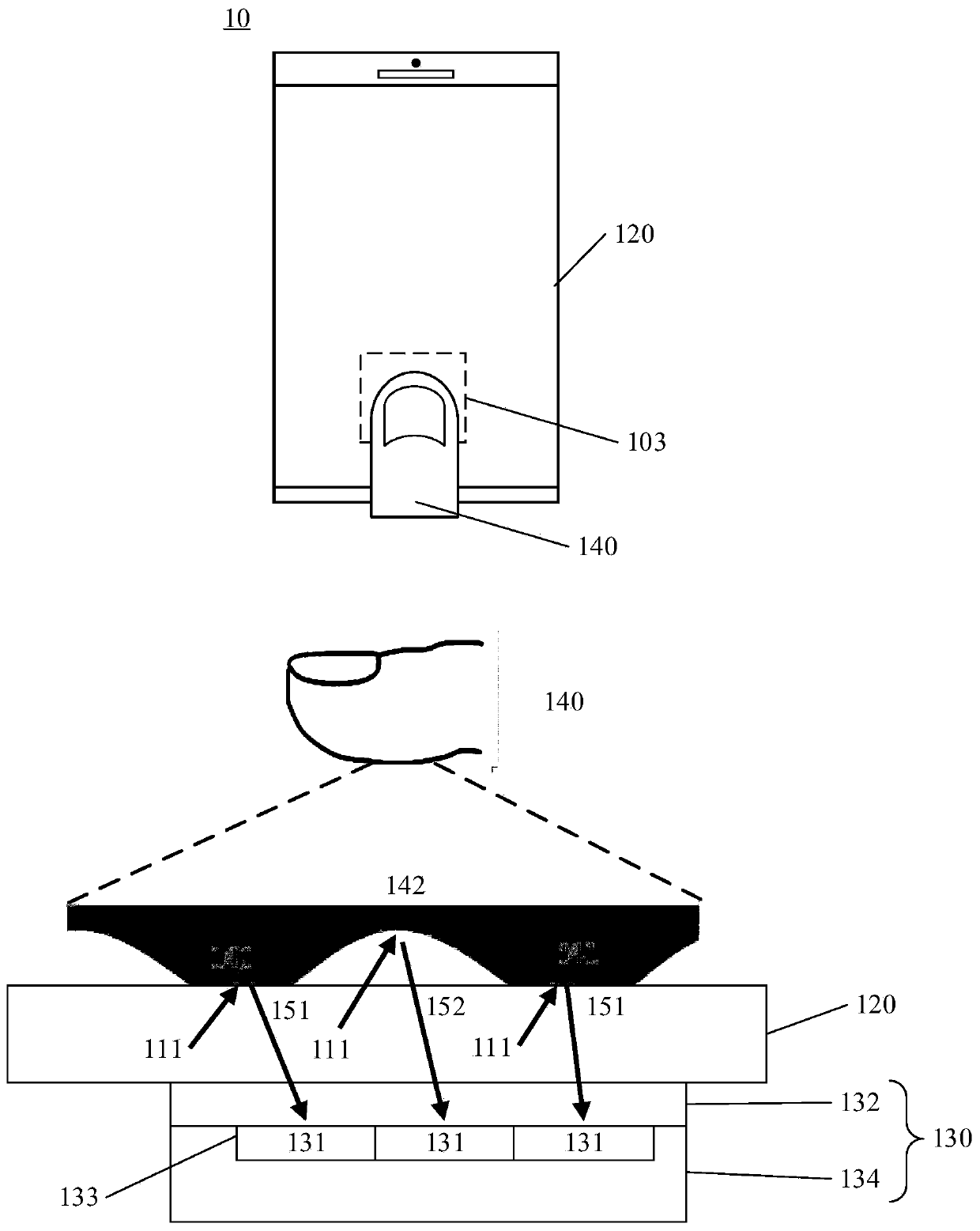
[0033] As a common application scenario, the optical fingerprint system provided in the embodiments of this application can be applied to smart phones, tablet computers, and other mobile terminals with display screens or other terminal devices; more specifically, in the abo...


PUM


Abstract

The embodiment of the present application provides a fingerprint identification device with a smaller thickness and a better imaging effect. The fingerprint recognition device includes: an optical path guiding structure disposed between the display screen and the optical fingerprint sensor for guiding an optical signal obliquely incident on the finger above the display screen and reflected by thefinger at a preset angle to an optical fingerprint sensor, disposed under the optical path guiding structure for detecting the received optical signal.

Description

technical field [0001] The present application relates to the field of information technology, and more specifically, to a fingerprint identification device and electronic equipment. Background technique [0002] Capacitive fingerprint recognition technology faces the limitation of penetrating ability, and it is difficult to apply to the fingerprint recognition system under the screen, while the optical fingerprint recognition technology breaks through the limitations of the thickness of the display screen and glass, so it has a good application prospect. [0003] In the optical fingerprint identification device, the optical path guide structure is usually used to guide the reflected light signal carrying the fingerprint information to the optical fingerprint sensor for collection, and the legitimacy of the user identity is confirmed by comparing the collected information with the pre-registered and stored fingerprint information. In order to meet the thinning requirements o...

Claims


Application Information

Patent Timeline
IPC IPC(8): G06K9/00
CPCG06V40/1318G06F21/32G06V40/1312G06V40/1335
Inventor 杜灿鸿
Owner SHENZHEN GOODIX TECH CO LTD
Why Eureka
Try Eureka