Check patentability & draft patents in minutes with Patsnap Eureka AI!

Chip center positioning fixture

A center positioning and chip technology, which is applied to coatings and devices for coating liquids on surfaces, etc., can solve the problems of long time, cumbersome process, high procurement cost, etc., to achieve simple operation, short time, and reduce misoperation. Effect

Active Publication Date: 2019-06-11
ZHUZHOU CRRC TIMES SEMICON CO LTD
View PDF8 Cites 1 Cited by
  • Summary
  • Abstract
  • Description
  • Claims
  • Application Information

AI Technical Summary

Problems solved by technology

[0004] like Figure 8 to Figure 11 As shown, the technical specifications of the support frame 1 and the clamping plate 2 correspond to the chips one by one, and the lengths of the support frame 1 corresponding to the chips 3 of different diameters are different; the lengths of the clamping plates 2 corresponding to the chips 3 of different diameters are The overall length is also different; and there are many kinds of chip 3 specifications in the production line, so chips 3 of different diameters need to be equipped with different support frames 1 and clamping plates 2, so in the process of uniform glue for different chips 3, it is necessary to Frequent replacement of different positioning fixtures; the process of tooling replacement is complicated and takes a long time
[0005] like Figure 12 As shown, in the replacement process, it is necessary to dismantle the two fixture set shells 6, the two clamping plates 2, and the two support frames 1, and then replace the two support frames 1 and the clamping plates 2 of another technical specification, and then Carry out center position calibration on it, and install two fixture group shells 6 after completion, at this moment the replacement work of fixture tooling just ends, and the whole process is relatively cumbersome, needs dismantling or installing 12 parts and 24 screws, needs professional equipment personnel to come complete and needs to be re-centered after each replacement
[0006] The replacement and adjustment of the center positioning fixture tooling is highly professional and difficult for the operator to master. Professional equipment personnel are needed to help them complete the fixture replacement, which takes up human resources; due to the replacement of the fixture tooling, frequent disassembly and assembly may easily cause the central position Deviations and screw holes slipping, resulting in inconsistent product process and equipment damage, and at the same time, the purchase cost of the accessories associated with the fixture is also relatively high

Method used


Image

  • Chip center positioning fixture
  • Chip center positioning fixture
  • Chip center positioning fixture

Examples


Embodiment Construction

[0034] The present invention will be further described below in conjunction with accompanying drawing.

[0035] It should be noted in this application that the term "multi-scale" used in this application refers to multiple sizes of chip diameters.

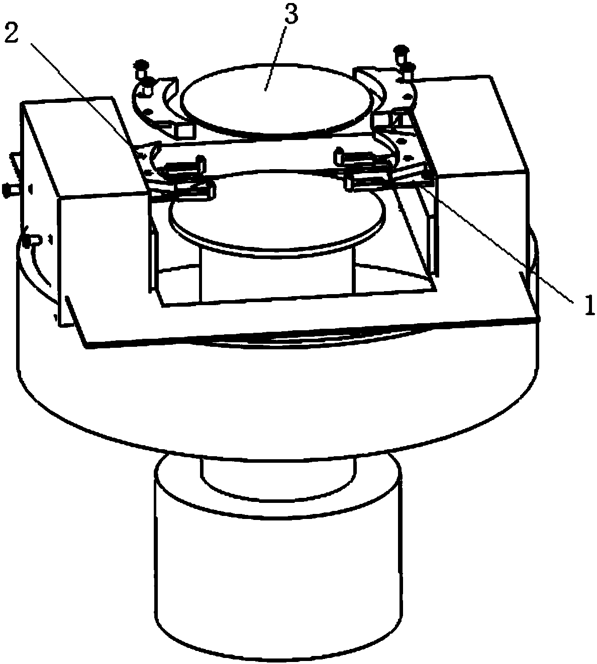
[0036] like figure 1 As shown, it is a schematic diagram of the assembly of the chip center positioning fixture of the present invention, including a support frame 1 and a clamping plate 2, the support frame 1 is placed on the bottom of the chip 3 for supporting the chip 3, and the clamping plate 2 is used for clamping the chip 3 The outer edge of the chip 3 is centered to ensure that the chip 3 will not be separated from the vacuum-adsorbed wafer table 4 due to centrifugal force when rotating at high speed; wherein, the support frame 1 and the clamping plate 2 are fixedly installed on the support block 5, Due to the step setting of the support block 5, the clamping plate 2 is located above the support frame 1. In addition, in th...


PUM


Abstract

The invention relates to a chip center positioning fixture. The chip center positioning fixture comprises a support frame arranged at the bottom of a chip for supporting the chip, and a clamping platelocated on the upper portion of the support frame for clamping the outer edge of the support frame; the support frame comprises a base bracket and an adjustment head; the adjustment head is arrangedon one side of the base bracket and can move horizontally relative to the base bracket so as to change the support range of the base bracket; the clamping plate comprises a base plate and a compositeplate; the composite plate can be detachably fixed at one end of the base plate for changing the clamping radius of the clamping plate. The support frame and the clamping plate of the fixture, so thatthe fixture is suitable for tools of chips of different diameters, compatibility of different fixtures of various specifications can be achieved, the time of replacing the fixture is greatly shortened, the equipment utilization efficiency is improved, the failure rate is lowered, thus, the fixture size replacement operation is more convenient, simpler and more time-saving; and in addition, the fixture tool is easy to manufacture and low in cost.

Description

technical field [0001] The invention belongs to the field of positioning devices, and in particular relates to a center positioning fixture applicable to chips of various diameters and sizes. Background technique [0002] Coating the photoresist evenly on the surface of the high-speed rotating chip is the uniform coating process; however, in the series of operations of the uniform coating process, one of the key steps is to center the chip before it rotates with the motor 7 at high speed. Positioning, so as to ensure that the chip will not break away from the vacuum-adsorbed wafer stage 4 due to centrifugal force when rotating at high speed. The center positioning jig tooling is a device to realize the accurate positioning of the center position of the chip on the equipment. The accuracy of the chip position depends on the adjustment of the alignment position of the equipment tooling. like Figure 7 As shown, it is a combination diagram of a traditional centering fixture to...

Claims


Application Information

Patent Timeline
IPC IPC(8): B05C13/02
Inventor 刘月雷田水宝尤新勇
Owner ZHUZHOU CRRC TIMES SEMICON CO LTD
Features
  • R&D
  • Intellectual Property
  • Life Sciences
  • Materials
  • Tech Scout
  • Unparalleled Data Quality
  • Higher Quality Content
  • 60% Fewer Hallucinations
Learn More