Dynamic coupling pure-electric drive axle and control method thereof

A pure electric drive and power coupling technology, applied in the direction of control devices, power devices, electric power devices, etc., can solve the problem of discounting the life of the hub motor in the cruising range of the car, increasing the unsprung mass, affecting the ride comfort, ride comfort and Handling stability and other issues to achieve the effect of improving vehicle economy, improving ride comfort, and reducing unsprung mass

Inactive Publication Date: 2019-06-11
SHANDONG UNIV OF TECH
View PDF9 Cites 3 Cited by
  • Summary
  • Abstract
  • Description
  • Claims
  • Application Information

AI Technical Summary

Problems solved by technology

However, because the hub motor is placed in the narrow wheel, it is limited by space, so the power of the hub motor is limited
If the load or speed of the car increases, the hub motor will run under heavy load or even overload, which will seriously affect the normal operation of the hub motor, resulting in a great reduction in the cruising range of the car and the life of the hub motor
At the same time, the wheel drive chassis structure will increase the unsprung mass of the car, which will affect the ride comfort, ride comfort and handling stability of the car.

Method used


Image

  • Dynamic coupling pure-electric drive axle and control method thereof
  • Dynamic coupling pure-electric drive axle and control method thereof
  • Dynamic coupling pure-electric drive axle and control method thereof

Examples


Embodiment 1

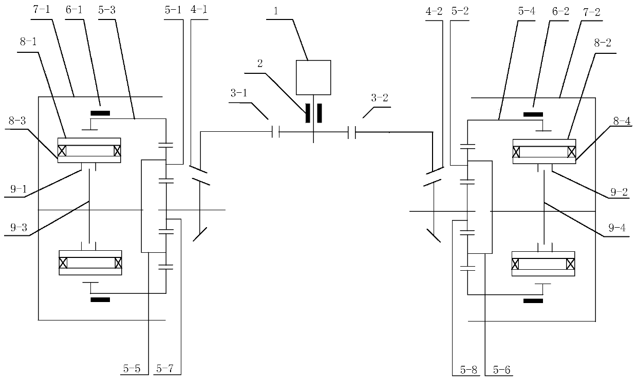
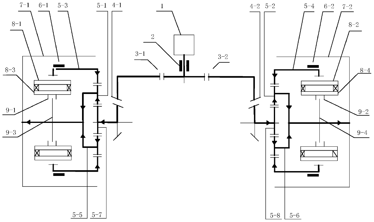
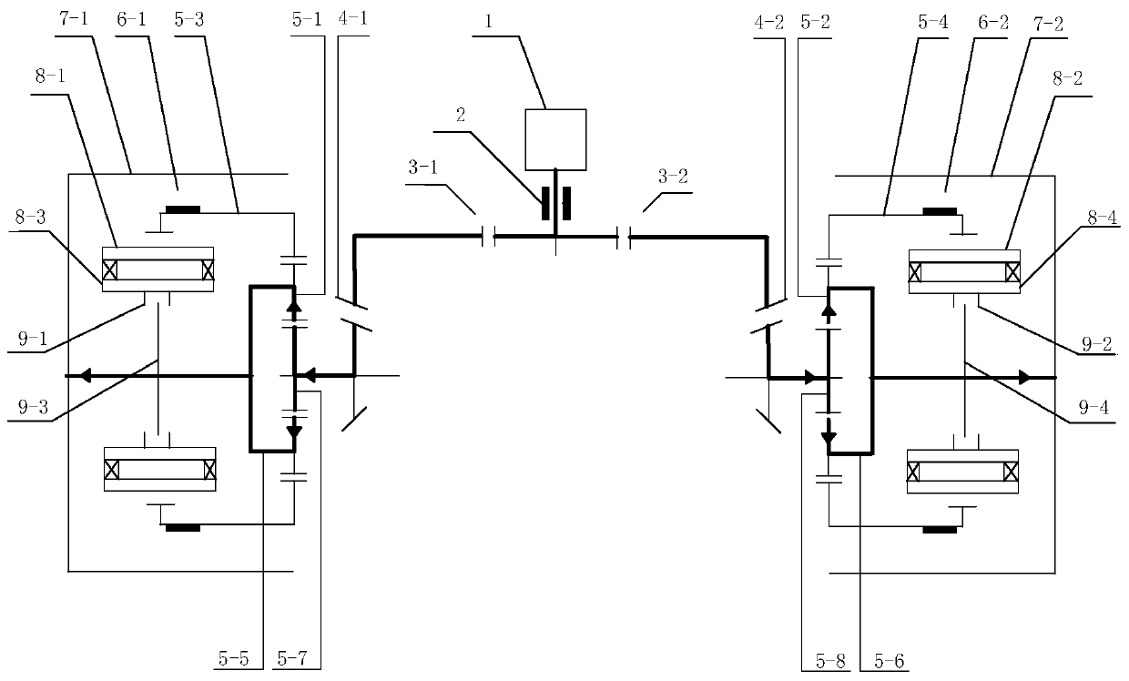
[0047] Left side: the output shaft of the central motor 1 is connected with the sun gear 5-7 of the left planetary mechanism 5 through the first brake 2, the fixed shaft transmission pair 3-1 and 4-1, and the rotor 8-1 of the left hub motor is connected with the The ring gear 5-3 of the left planetary mechanism 5 is connected, the second brake 6-1 can control the output of the ring gear 5-3 and the left hub motor, and the planet carrier 5-5 of the left planetary mechanism 5 passes through the left The power transmission shaft is connected with the rim 7-1, and the brake caliper 9-1 of the third brake 9 on the left is installed on the motor housing of the left hub motor 8, and the brake disc 9-3 is connected with the left power transmission shaft. Wherein the first brake can control the output of the central motor, the second brake 6-1 can control the output of the left ring gear and hub motor, and the third brake on the left can control the movement of the left wheel.

[0048] R...

Embodiment 2

[0114] Such as Figure 7 As shown: the difference between this embodiment and embodiment 1 is that the first brake 2 in embodiment 1 is removed, and at the transmission shaft between the sun gear of the planetary mechanism on the left and right sides and the fixed shaft gear transmission pair 4 A fourth brake 10 is added respectively. This embodiment can realize all the modes of Embodiment 1, and its specific working principle and speed ratio calculation are the same as those of Example 1, and will not be repeated here.

Embodiment 3

[0116] Such as Figure 8 Shown: this embodiment removes the structural principle diagram of the first brake 2 on the basis of embodiment 1.

[0117] In this embodiment, except that the in-wheel motor driving mode and the in-wheel motor regenerative braking mode in embodiment 1 cannot be realized, other modes in embodiment 1 can be realized by this mode, and its specific working principle and speed ratio calculation relationship are the same as Embodiment 1 is the same and will not be repeated here.


PUM


Abstract

The invention discloses a dynamic coupling pure-electric drive axle and a control method thereof. The drive axle mainly comprises a central motor, two hub motors, two planet mechanisms, five brakes and four dead axle gear pairs. A sun gear and a gear ring of three elements of each planet mechanism serve as two input ends or one element serves as an input end, and a planet carrier of each planet mechanism serves as an output end. The central motor is connected with the sun gears of the planet mechanisms on the corresponding sides through two corresponding dead axle gear pairs, the two hub motors are connected with the gear rings of the planet mechanisms on the corresponding sides, the planet carriers on the two sides are connected with rims on the corresponding sides through transmission shafts to serve as output ends, power is finally transmitted to the rims through the planet carriers, and a vehicle is driven to run. By the adoption of the structural scheme, different working modes can be achieved according to the actual road condition requirements, the high requirement of the vehicle for the dynamic property can be met, a power source works in an efficient area, and the economical efficiency of the vehicle is improved. Meanwhile, the unsprung mass of the vehicle is reduced, and the riding comfort and control stability of the vehicle are improved.

Description

technical field [0001] The invention relates to a vehicle drive axle and a control method thereof, in particular to a power coupling pure electric drive axle for an electric vehicle and a control method thereof. Background technique [0002] With the continuous increase in the number of cars, the shortage of petrochemical energy has appeared before people's eyes. The exhaust gas emitted by traditional cars has made the environmental pollution for human living more and more serious. The transformation of automobiles is also an inevitable trend in the development of the automobile industry. [0003] At present, most domestic electric vehicle companies are driven by central motors. In fact, they have transformed from traditional vehicles. There are still mechanical components such as clutches, transmissions, reducers, and differentials in traditional vehicles, which makes power transmission inefficient. , a serious waste of energy. Due to the limitation of motor power and bat...

Claims


Application Information

Patent Timeline
Patent Type & Authority Applications(China)
IPC IPC(8): B60K1/02B60K7/00B60K17/04
Inventor 谭迪刘帅帅
Owner SHANDONG UNIV OF TECH
Why Eureka
Try Eureka