Ventilation and cooling performance configuration method, device and tower for high tower tower

A technology of ventilation cooling and configuration method, which is applied to wind power generation, wind turbines, machines/engines, etc., can solve the problems of different heat dissipation, timely discharge of heat from towers, and high towers, and achieves a simple configuration method, improves ventilation performance, Efficient effect

Active Publication Date: 2020-10-16
CSR ZHUZHOU ELECTRIC LOCOMOTIVE RES INST
View PDF6 Cites 0 Cited by
  • Summary
  • Abstract
  • Description
  • Claims
  • Application Information

AI Technical Summary

Problems solved by technology

For the ventilation and heat dissipation performance of the high tower, the ventilation and heat dissipation structure of the original tower is usually used directly at present, that is, the heat dissipation system configured by the ventilation and heat dissipation mode of the traditional ordinary height tower is directly used. As the height increases, the heat transfer area of ​​the tower increases, and the external heat transfer capacity of the tower wall increases, so the high tower can improve the ventilation and heat dissipation performance to a certain extent, but due to the increase of the tower, the hot air emitted by the converter rises At the same time, the path will also increase and the resistance will increase. If the ventilation and heat dissipation structure of the original tower is used directly, the hot air discharged from the converter will accumulate on the first layer of the tower and cause the temperature to rise, and the high tower structure is not conducive to the heat dissipation of the tower. The timely discharge makes the ventilation and cooling performance poor, and when the ambient temperature is too high, it is easy to cause problems such as excessive local temperature in the space inside the tower.
[0004] In order to solve the above-mentioned technical problems of the high-rise tower, adding equipment such as cooling fans in the tower can improve the ventilation and cooling performance, but the air volume and heat dissipation of the cooling fans are different, and the ventilation and cooling generated in the entire elevated tower The effect is also different. If the layout position and air volume of the cooling fan do not match the air volume entering and exiting the tower, the air in the upper layer will be poured back from the elevator hole to the lower layer, so that the cooling fan needs to do more work, but the ventilation and cooling performance is still poor.

Method used


Image

  • Ventilation and cooling performance configuration method, device and tower for high tower tower
  • Ventilation and cooling performance configuration method, device and tower for high tower tower
  • Ventilation and cooling performance configuration method, device and tower for high tower tower

Examples


Embodiment 1

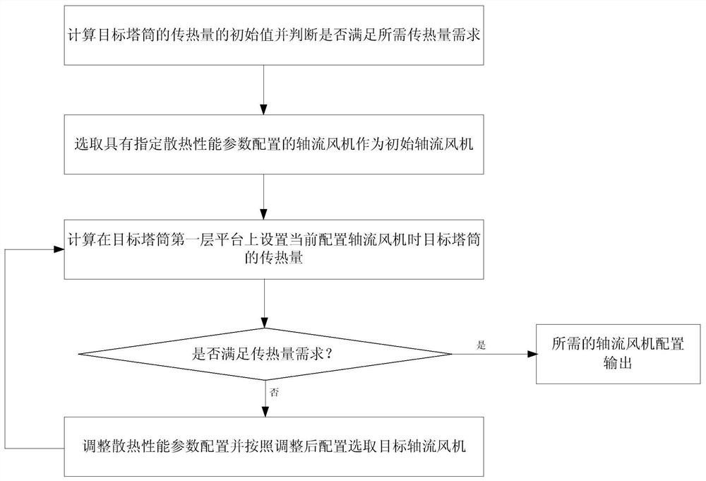
[0064] Such as figure 1 As shown, this embodiment is used for the ventilation and cooling performance configuration method of a high tower tower, and the steps include:

[0065] S1. Calculate the initial value of the heat transfer value of the target tower and judge whether the required heat transfer requirement is met, if not, proceed to step S2;

[0066] S2. Select an axial flow fan with a specified heat dissipation performance parameter configuration as the initial axial flow fan;

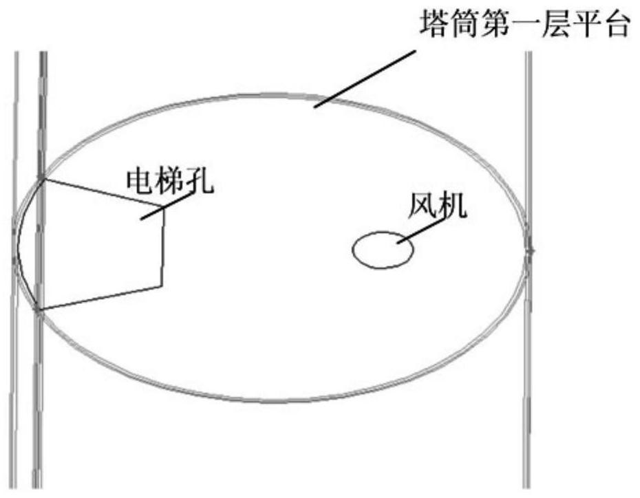
[0067] S3. Calculate the heat transfer of the target tower when the axial flow fan is currently configured on the first platform of the target tower, and judge whether the required heat transfer is met. If not, adjust the heat dissipation performance parameter configuration and follow the adjusted configuration Select the target axial flow fan, return to step S3, and output the required heat dissipation performance parameter configuration of the axial flow fan if it is satisfied.

[0068] In t...

Embodiment 2

[0126] Hereinafter, the present invention will be further described by taking the ventilation and cooling performance configuration of a 2MW double-fed high-tower wind power generating set as an example.

[0127] Step 1: Determine the calculation conditions according to the structure and materials of the tower, the configuration and requirements of the ventilation and cooling system of the converter, and the design ambient temperature. The specific calculation parameters for the heat transfer capacity of the tower wall are shown in Table 1.

[0128] Table 1: Parameter setting table for calculating the heat transfer capacity of the tower wall.

[0129]

[0130]

[0131] Step 2: Calculate the heat transfer coefficient of the tower according to the structure of the tower.

[0132]According to the configuration in Table 1, the air convection heat dissipation method in the tower is regarded as forced convection in the tube, and the convective heat transfer coefficient Kin is ...


PUM


Abstract

The invention discloses a high tower tube ventilation cooling performance setting method and device and a tower tube. The method comprises the steps that S1, an initial value of the heat transfer amount of the target tower tube is calculated, and whether the heat transfer amount meets the required heat transfer amount demand or not is judged, and if not, the process goes to step S2; S2, an axial flow fan with specified radiating performance parameter setting is selected as an initial axial flow fan; and S3, the heat transfer amount of the target tower when the axial flow fan with the current setting is arranged on a first layer of platform of the target tower tube is calculated, whether the heat transfer amount meets the required heat transfer amount demand or not is judged, if not, the radiating performance parameter setting is adjusted, and the process returns to step S3, and if yes, the required axial flow fan setting is output. The device comprises a tower tube heat transfer amountjudgment unit, a selection unit and a judgment adjustment unit. Through the method and device, optimal setting of the tower tube ventilation cooling performance can be achieved in combination with the heat transfer characteristics of the high tower tube, and the advantages of the simple implementation method, high setting efficiency, good effect and the like are achieved.

Description

technical field [0001] The invention relates to the technical field of high towers of wind turbines, in particular to a ventilation cooling performance configuration method, device and tower for high towers. Background technique [0002] The converter and other electrical components in the wind turbine tower will generate a lot of heat during operation, and ventilation and cooling design is required to achieve effective heat dissipation. At present, the wind turbine tower usually directly relies on the chimney effect of hot air and the tower arm to achieve ventilation and cooling, or uses the ventilation and heat dissipation structure of the air-cooled converter itself in the high tower tower, that is, through the reasonable arrangement of the components of the cabinet To enhance the ventilation and cooling of the converter, but the heat exchange capacity of the above method is limited, the high-temperature gas generated during the operation of the converter cannot be cooled...

Claims


Application Information

Patent Timeline
Patent Type & Authority Patents(China)
IPC IPC(8): F03D80/60G06F30/20G06F119/08
CPCY02E10/72
Inventor 欧阳华董红云宋力兵陈少敏汤腾蛟
Owner CSR ZHUZHOU ELECTRIC LOCOMOTIVE RES INST
Why Eureka
Try Eureka