Slow wave structure applicable to millimeter-wave terahertz-band multi-electron beam return wave pipe

A slow-wave structure and terahertz technology, applied in the field of slow-wave structures, can solve problems such as strong competition between modes, inability to expand arbitrarily, complex modes, etc., achieve easy adjustment of coupling impedance, solve mode competition problems, and simple geometric structure Effect

Active Publication Date: 2019-06-11
UNIV OF ELECTRONICS SCI & TECH OF CHINA
View PDF4 Cites 6 Cited by
  • Summary
  • Abstract
  • Description
  • Claims
  • Application Information

AI Technical Summary

Problems solved by technology

Among them, the ridge waveguide slow wave structure such as figure 1 As shown, its bandwidth is wide, but the coupling impedance is low. The schematic diagram of the slow wave structure with two ridge waveguide units connected in parallel is shown in Figure 5 As shown, its structural dispersion curve is shown as Image 6 As shown, the upper cut-off frequency of the working mode Mode2 is the same as that of the non-working mode Mode1, and the lower cut-off frequency is different. Working between 180° and 280° phase shift per cycle will cause strong mode competition
It can be seen that when the ridge waveguide slow wave structure is connected in parallel, there will be many high-order strong competition modes, and the tube cannot work stably
Solving the mode competition requires shifting the operating frequency band in the direction of increasing phase shift per cycle, which results in smaller structures that cannot be processed
The schematic diagram of a rectangular single gate structure is shown in figure 2 As shown, it is the slow wave structure commonly used in millimeter-wave terahertz return wave tubes. Its coupling impedance attenuates sharply after leaving the grid surface. It can only work effectively when the electron beam is very close to the grid surface, and its lateral size is limited by the wavelength. , cannot be expanded arbitrarily, so cannot work in parallel
The schematic diagram of the trapezoidal line slow wave structure is shown in image 3 As shown, the front view of the multi-conductor slow-wave structure is as follows Figure 4 As shown, the coupling impedance of the two is high. After parallel connection, the existing modes are complex, and the basic characteristics of the dispersion of the parallel structure are similar to those of the ridge waveguide. The competition between the modes is strong, and it is impossible to work stably with multiple injections.
Therefore, the parallel connection of existing slow-wave structures either has low coupling degree or serious mode competition

Method used


Image

  • Slow wave structure applicable to millimeter-wave terahertz-band multi-electron beam return wave pipe
  • Slow wave structure applicable to millimeter-wave terahertz-band multi-electron beam return wave pipe
  • Slow wave structure applicable to millimeter-wave terahertz-band multi-electron beam return wave pipe

Examples


Embodiment 1

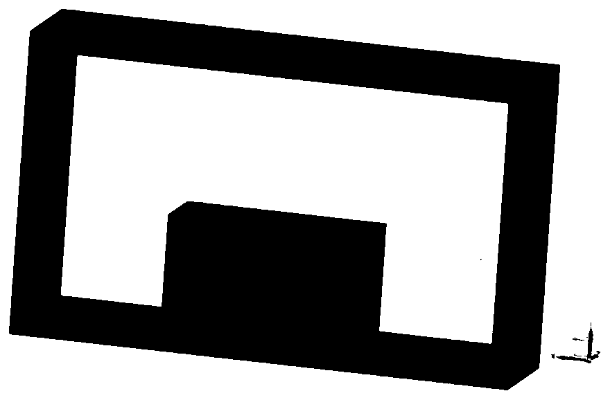
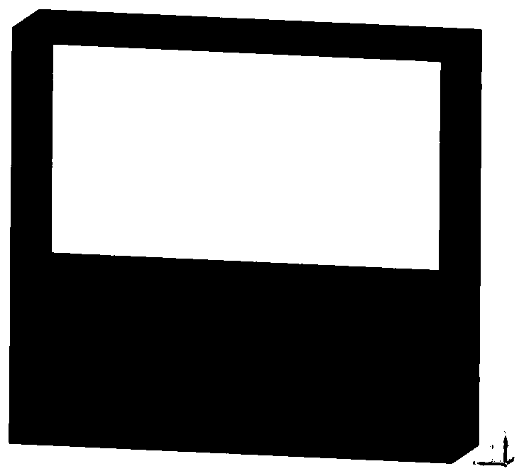
[0041] Figure 7 It is a schematic diagram of a single period of the slow wave structure of Example 1 of the present invention, that is, a schematic diagram of a slow wave structural unit. As shown in the figure, the present invention includes a rectangular waveguide 71, a unit ridge composed of rectangular grid teeth 72 and 73 arranged and extended periodically along the axial direction on the lower bottom surface and the upper top surface of the rectangular waveguide, and band-shaped electronic bands on the left and right sides of the unit ridge. Note channels 74 and 75. The main function of the rectangular waveguide is to support the internal structure and transmit electromagnetic waves; the electron beam channel is the empty part inside the rectangular waveguide 71, which is filled with air, and the above structure constitutes a complete slow wave structure. Specific dimensions such as Figure 9 , Figure 10 as shown ( Figure 9 is the front view of the structure, Fi...

Embodiment 2

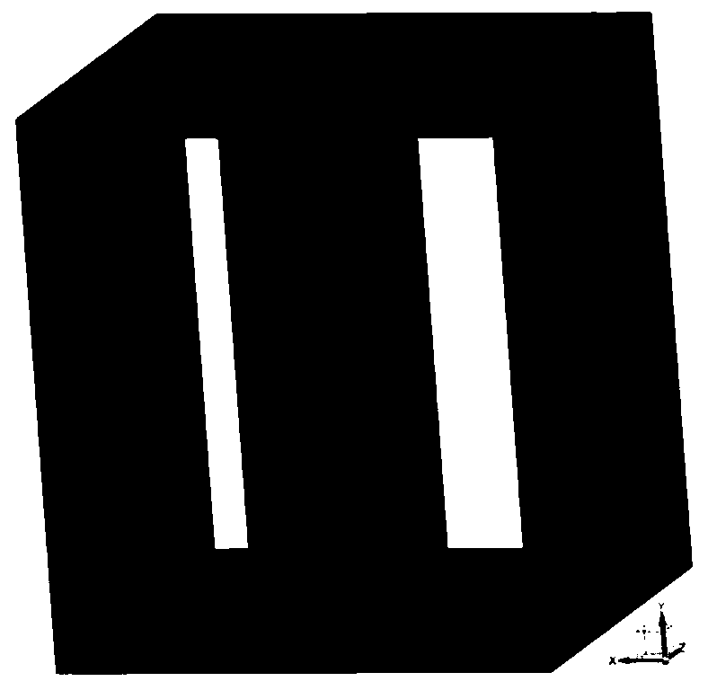
[0045] Figure 11 , Figure 12 It is a schematic diagram of the slow wave structure of the parallel coupled multi-electron injector return wave tube. The structure shown in the figure is the unit ridge structure in Embodiment 1 formed in parallel along the vertical direction or along the horizontal direction. The multi-beam coupling slow wave structure formed by this parallel connection can shorten the saturated tube length and increase the output power. Its bandwidth, dispersion characteristics and coupling impedance are the same as Figure 7 The slow wave structure shown is similar. Figure 15 , Figure 16 It is the dispersion curve and normalized phase velocity curve of the multi-electron injector return wave tube slow wave structure coupled in parallel in the horizontal direction. The figure shows that the Mode1 frequency band of this slow wave structure is 747-1038GHz, and the Mode2 frequency band is 755-1038GHz. The Mode3 frequency band ranges from 755-1279GHz, and ...


PUM


Abstract

The invention provides a slow wave structure applicable to a millimeter-wave terahertz-band multi-electron beam return wave pipe. The slow wave structure can be applicable to a millimeter terahertz band and belongs to the field of a microwave vacuum electronic device. In the structure, two fixedly-connected metal gating teeth form a unit ridge, a plurality of unit ridges are periodically arrangedto form a ridge, and the ridge and a rectangular waveguide structure form the slow wave structure. The structure combines the structural characteristics of a ridge waveguide, the rectangular waveguideand a trapezoid line to form a novel slow wave structure. The structure after the slow wave structure is connected in parallel is similar to a multi-conductor slow wave structure, the advantage liesin that the coupling impedance is easy to adjust; by an appropriate parameter design, relatively large coupling impedance can be achieved; the attenuation speed of the coupling impedance in a direction far away from a grate surface is relatively low, a relatively large-area electron beam can be achieved, higher output power is further achieved, and the horizontal size is free from the limitation of wavelength and can be arbitrarily expanded.

Description

technical field [0001] The invention belongs to the field of microwave vacuum electronic devices, and in particular relates to a slow-wave structure suitable for a multi-electron injector return-wave tube in the millimeter-wave terahertz frequency band. The slow-wave structure can use a plurality of strip electron beams to work. Background technique [0002] As the core component of the Cherenkov electric vacuum device, the slow wave structure is an important place for the interaction between the electron beam and the electromagnetic wave. Because of the size co-transition effect, when the operating frequency of the device rises to the millimeter wave and terahertz frequency bands, the geometric size of the slow wave structure will decrease sharply, which greatly reduces the available current of the slow wave structure and makes processing difficult. Coupled with the reduction of coupling impedance and the shortening of wavelength, the effective charge amount of cluster clus...

Claims


Application Information

Patent Timeline
Patent Type & Authority Applications(China)
IPC IPC(8): H01J23/24
Inventor 程均殷海荣徐进岳玲娜赵国庆王文祥魏彦玉
Owner UNIV OF ELECTRONICS SCI & TECH OF CHINA
Why Eureka
Try Eureka