
Anti-saliency tangentially magnetized multi-phase permanent magnet fault-tolerant motor

A permanent magnet fault-tolerant, salient-pole technology, applied in synchronous motors with static armatures and rotating magnets, synchronous machine parts, magnetic circuit rotating parts, etc., can solve the mutual constraints between normal operation performance and fault tolerance, etc. problem, to achieve excellent normal operation performance and fault-tolerant operation ability, reduce permanent magnetic flux, change the effect of air gap magnetic density

Active Publication Date: 2021-03-02
HARBIN INST OF TECH
View PDF8 Cites 0 Cited by
  • Summary
  • Abstract
  • Description
  • Claims
  • Application Information

AI Technical Summary

Problems solved by technology

[0003] The purpose of the present invention is to solve the problem of mutual restriction between normal operation performance and fault tolerance capability in traditional multiphase permanent magnet fault-tolerant motors, and to provide an anti-saliency tangentially magnetized multiphase permanent magnet motor with excellent operation performance and fault tolerance capability. Magnetic Fault Tolerant Motor

Method used


Image

  • Anti-saliency tangentially magnetized multi-phase permanent magnet fault-tolerant motor
  • Anti-saliency tangentially magnetized multi-phase permanent magnet fault-tolerant motor
  • Anti-saliency tangentially magnetized multi-phase permanent magnet fault-tolerant motor

Examples


specific Embodiment approach 1

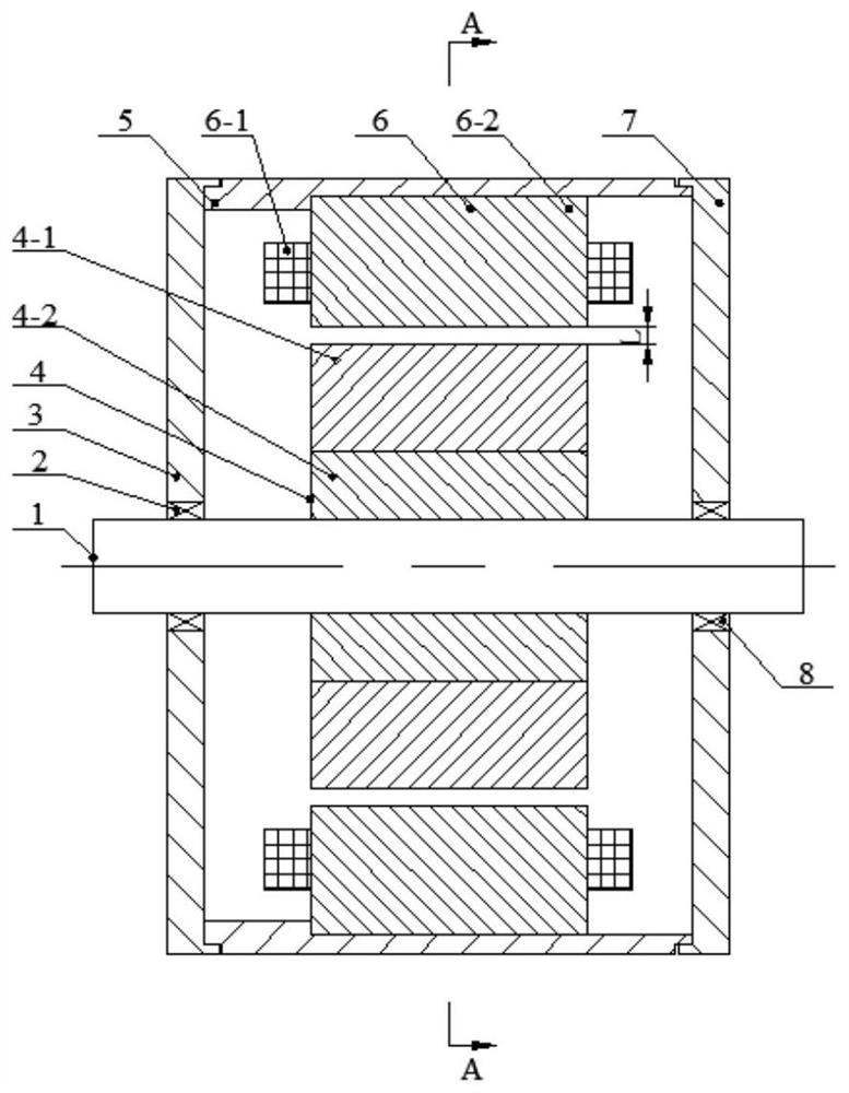
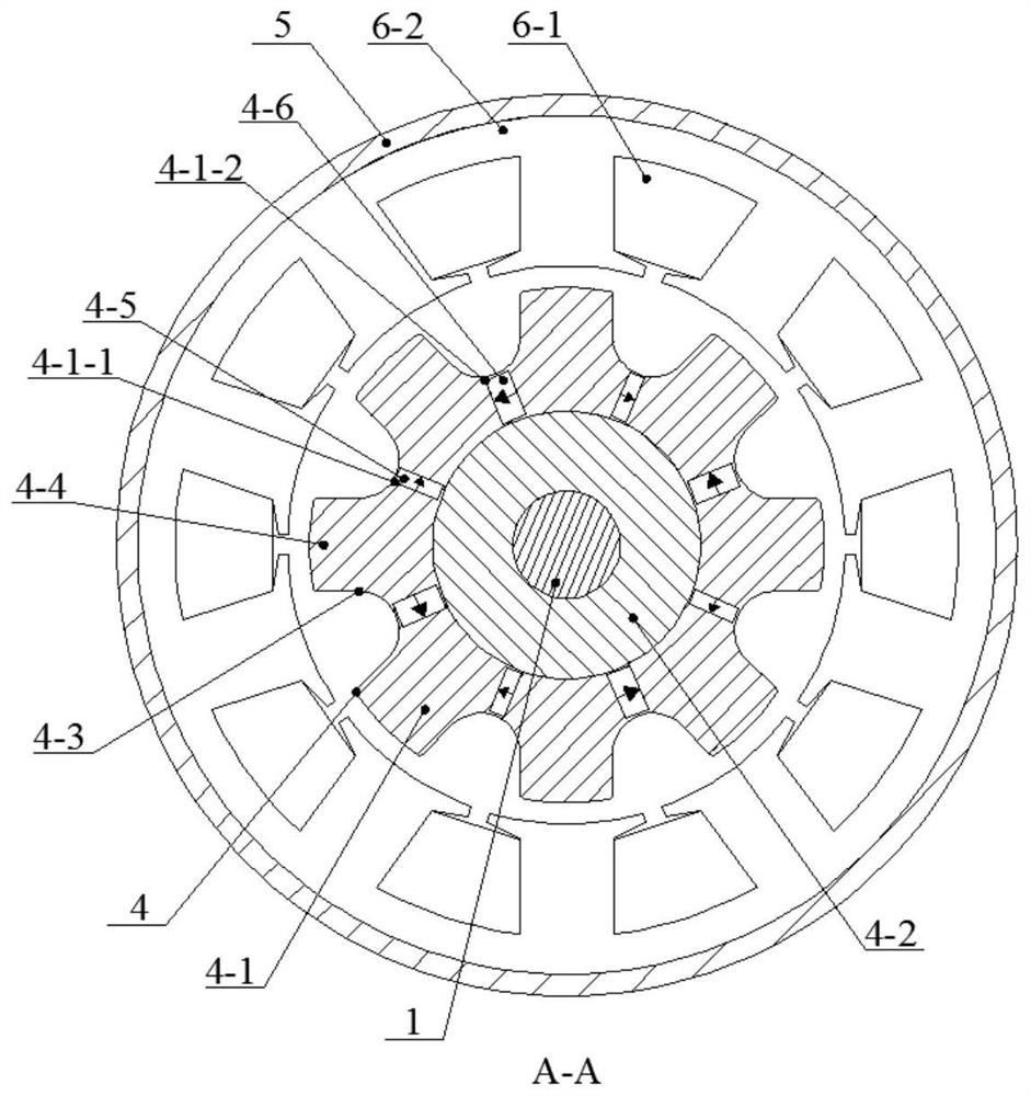
[0019] Specific implementation mode one: the following combination Figure 1 to Figure 2 Describe this embodiment. This embodiment includes a rotating shaft 1, a first bearing 2, a left end cover 3, a rotor 4, a casing 5, a stator 6, a right end cover 7, and a second bearing 8. The direct axis reactance of the motor is greater than the quadrature axis reactance;

[0020] The ports on the left and right sides of the casing 5 are respectively provided with a left end cover 3 and a right end cover 7, the stator 6 is fixed on the inner wall of the casing 5, the rotor 4 is fixed on the rotating shaft 1, and the rotating shaft 1 passes through the first bearing 2 and the second bearing 8 are respectively rotated and fixed on the left end cover 3 and the right end cover 7, and there is a radial air gap L between the rotor 4 and the stator 6;

[0021] The stator 6 includes a stator core 6-2 and an m-phase stator winding 6-1. The stator winding 6-1 is a multi-phase fractional slot conc...

Embodiment approach 2

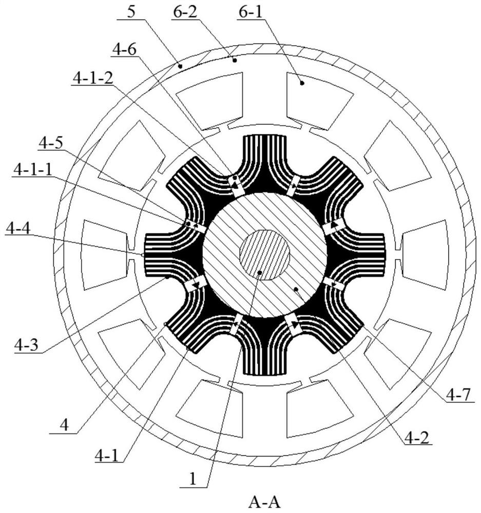
[0033] Implementation mode two: the following combination figure 1 and image 3 This embodiment will be described. The difference from Embodiment 1 is that in this embodiment, there are multiple arc-shaped magnetic barrier slots 4-7 on the 2p ferromagnetic poles 4-4, and the multiple magnetic barrier slots 4-7 are sequentially arranged along the radial direction. Arranged and symmetrical with respect to the first permanent magnet pole slot 4-1-1 or the second permanent magnet pole slot 4-1-2.

[0034] By arranging multiple magnetic barrier slots 4-7, the difference between the direct axis inductance and the quadrature axis inductance can be further increased, which is beneficial to increase the reluctance torque of the motor.

specific Embodiment approach 3

[0035] Embodiment 3: The difference between this embodiment and Embodiment 1 is that in this embodiment, a certain phase winding in the m-phase stator winding 6-1 has a short-circuit fault, and the multi-phase full-bridge inverter will The end of the faulty phase winding is short-circuited, and at the same time, the current in the remaining m-1 phase normal windings in the stator winding 6-1 is controlled to control the magnetic state of the p second permanent magnets 4-6, so that the p second permanent magnets 4-6 The operating point of the permanent magnets 4-6 is lowered, and even reversely magnetized to reduce the size of the permanent magnetic field in the air gap, thereby suppressing the short-circuit current of the faulty phase winding.


PUM


Abstract

The invention relates to an anti-saliency tangentially magnetized multiphase permanent magnet fault-tolerant motor, which belongs to the field of permanent magnet fault-tolerant motors. The invention solves the problem of mutual restriction between normal operation performance and fault-tolerant capability in traditional multi-phase permanent magnet fault-tolerant motors. The direct-axis reactance of the motor of the present invention is greater than the quadrature-axis reactance; the outer surface of the rotor iron core of the rotor is evenly opened with p completely consistent rotor grooves, and 2p ferromagnetic poles are formed between the 2p rotor grooves, and between two adjacent iron poles The yoke of the rotor core between the magnetic poles is alternately opened with 2p slots along the radial direction; p first permanent magnets and p second permanent magnets are embedded in the 2p slots alternately; the magnetic isolation ring is fixed on the shaft, and the rotor The iron core is fixed on the outer circular surface of the magnetic isolation ring; by adjusting the current in the stator winding to change the operating point of the p second permanent magnets to change the magnitude or direction of the magnetic flux, and then realize the pairing of p second permanent magnets to p The permanent magnetic field of the first permanent magnet in the air gap L is positively or reversely superimposed.

Description

technical field [0001] The invention belongs to the field of permanent magnet fault-tolerant motors. Background technique [0002] Permanent magnet motors are widely used in many fields such as electric vehicles and wind power generation due to their advantages of high efficiency and high power density. Compared with the traditional three-phase permanent magnet synchronous motor, the multi-phase permanent magnet fault-tolerant motor has good fault-tolerant operation ability because of its redundant phase number. Different from the traditional permanent magnet motor, when designing a multi-phase permanent magnet fault-tolerant motor, it is necessary to ensure that the electrical, magnetic, thermal and physical isolation conditions are met between the different phase windings. Only in this way can the faulty winding be separated when a fault occurs Effective isolation from other normal phase windings. At the same time, the current of other normal phase windings is controlled...

Claims


Application Information

Patent Timeline
Patent Type & Authority Patents(China)
IPC IPC(8): H02K1/27H02K1/16H02K21/14H02K21/02
Inventor 隋义刘勇郑萍尹佐生刘国鹏
Owner HARBIN INST OF TECH
Learn More