
Method of Ultrasonic CT Sound Velocity Imaging Based on Prior Reflection Imaging

A sound velocity and imaging technology, applied in ultrasonic/sonic/infrasonic image/data processing, ultrasonic/sonic/infrasonic Permian technology, computerized tomography scanner, etc. The result is too smooth and other problems, to reduce the amount of calculation and reduce the effect of error

Active Publication Date: 2020-05-22
苏州二向箔科技有限公司
View PDF10 Cites 0 Cited by
  • Summary
  • Abstract
  • Description
  • Claims
  • Application Information

AI Technical Summary

Problems solved by technology

For example, the existing sound velocity imaging methods based on transmitted waves are more representative of joint algebraic reconstruction method (SART) and Tychonov regularization reconstruction method. influence, the reconstruction results are not accurate enough; the latter has higher requirements for the selection of regularization parameters, and the reconstruction results are often too smooth, easy to lose some key information, and generally cannot reach a satisfactory level

Method used


Image

  • Method of Ultrasonic CT Sound Velocity Imaging Based on Prior Reflection Imaging
  • Method of Ultrasonic CT Sound Velocity Imaging Based on Prior Reflection Imaging
  • Method of Ultrasonic CT Sound Velocity Imaging Based on Prior Reflection Imaging

Examples


Embodiment Construction

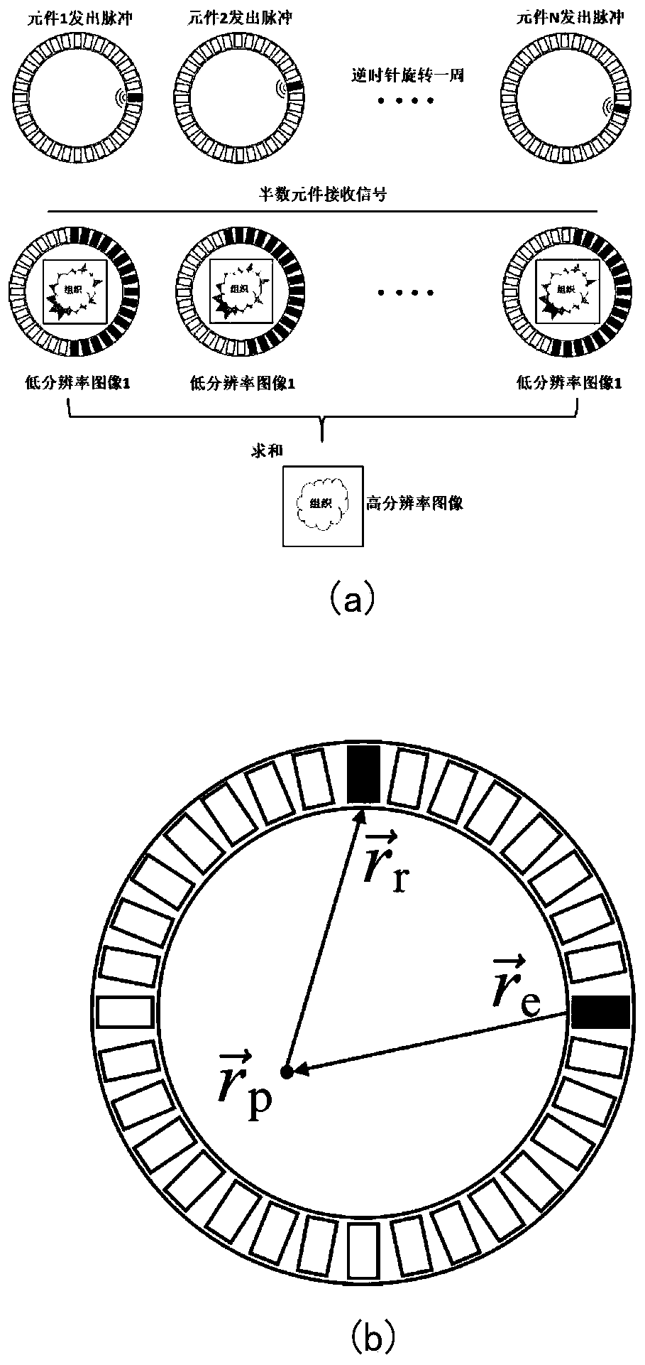
[0028] The technical solutions in the embodiments of the application will be clearly and completely described below in conjunction with the accompanying drawings in the embodiments of the application. Obviously, the described embodiments are only for illustration and are not intended to limit the application.

[0029] In order to realize the reconstruction of the image of the sound velocity distribution inside the tissue, the present invention provides a method of ultrasonic CT sound velocity imaging based on prior reflection imaging. First, a plurality of piezoelectric ultrasonic transducers are surrounded in a circular array to surround the target body (in this example, breast), and put them into the water tank (which contains water); secondly, make each ultrasonic transducer (as a transmitter) send pulsed sound wave signals in turn, and at the same time, other ultrasonic transducers (as a receiver) receive The original data is obtained from the signal; finally, the received ...


PUM


Abstract

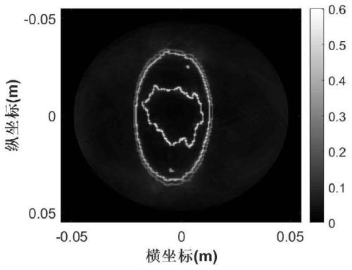
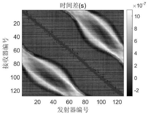
The invention discloses an ultrasonic CT sound velocity imaging method based on prior reflection imaging. The method comprises the steps of: obtaining raw data received by a piezoelectric ultrasonic transducer array; and using the original data to perform reflection imaging by using an aperture synthesis method to obtain a reflection image with higher resolution, and obtaining a position of a region occupied by a medium water; obtaining a travel time difference map; discretizing an object to-be-tested into N*N grids, obtaining a coefficient projection matrix by bilinear interpolation, and establishing a linear equation model with N*N unknowns; solving a linear equation model by total variation regularization, and obtaining the reconstruction result of the sound velocity in an area to-be-tested. The method not only greatly reduces the area to-be-reconstructed, but also improves the quality of the reconstructed image in an ultrasonic CT sound velocity imaging technology so as to be closer to the true sound velocity distribution.

Description

technical field [0001] The application belongs to the technical field of ultrasonic CT imaging in biomedical ultrasonics, and more specifically relates to a method for ultrasonic CT sound velocity imaging based on prior reflection imaging. Background technique [0002] Ultrasonic CT imaging examination method has the advantages of non-invasive, radiation-free, and does not depend on the operation of doctors, so it has a good application prospect. The basic starting point of this technology is to detect the structure distribution of the target body by sending and receiving ultrasonic waves. The received signal contains a large amount of information related to the medium parameters of the target body. Based on the signal detected by the sensor, we can reconstruct the medium parameter information of the target body we need through some corresponding algorithms. The commonly used sound velocity , attenuation coefficient, etc. [0003] Ultrasonic CT imaging has a variety of mod...

Claims


Application Information

Patent Timeline
Patent Type & Authority Patents(China)
IPC IPC(8): A61B8/08A61B6/03
Inventor 屈晓磊姚子升樊尚春
Owner 苏州二向箔科技有限公司
Learn More