
Ureteral stent

A technology for ureters and tubular components, applied in the field of ureteral stents, which can solve problems such as irritation of the trigone of the bladder and discomfort of patients

Active Publication Date: 2019-06-14
GYRUS ACMI INC (D B A OLYMPUS SURGICAL TECH AMERICA)
View PDF24 Cites 2 Cited by
  • Summary
  • Abstract
  • Description
  • Claims
  • Application Information

AI Technical Summary

Problems solved by technology

However, one or both of these retention features can have adverse effects or patient discomfort, including: bleeding, persistent urge to urinate, and irritation of the trigone

Method used


Image

  • Ureteral stent
  • Ureteral stent
  • Ureteral stent

Examples


Embodiment Construction

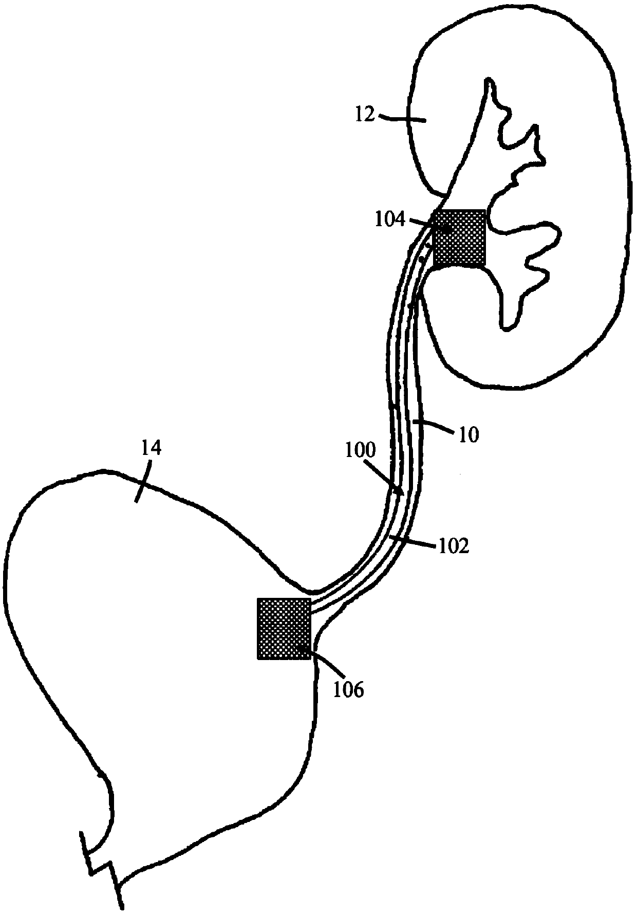
[0022] These teachings relate to stents. The stent can be a medical stent. The stent can be any stent, such as a ureteral stent. Ureteral stents are used to aid in the drainage of fluid or urine from the patient's kidneys to the bladder. For example, following some medical procedures for ureteral stones or tumors, fragments or fragments of the stone or tumor can fall down into the ureter, which can interrupt or block the flow of urine from the kidney to the bladder. A ureteral stent acts to allow dilation of the ureter, which allows stones or stone fragments to pass through and allows fluid or urine to flow from the kidney to the bladder.

[0023] The stent can include a tubular member. The tubular member can be placed in the patient's urethra. The tubular member may extend between two opposite ends, one or both of which may be retaining ends. The tubular member may be a generally hollow member comprising a through hole, opening or lumen extending from one retaining end t...


PUM


Abstract

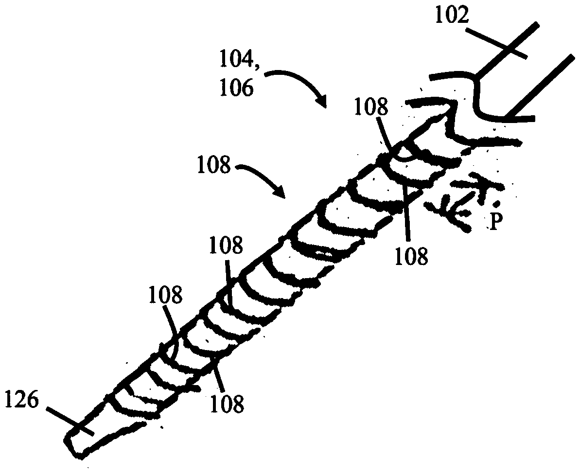
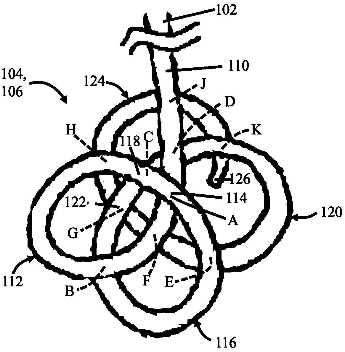
The subject of the invention is a ureteral stent. The invention discloses a ureteral stent that includes a tubular member and a retaining end adapted to be placed inside a kidney or a bladder of a patient. The retaining end includes a plurality of loops. Each of the loops is centered about a loop axis, and two or more of the loop axes extend in different directions relative to other loop axes.

Description

technical field [0001] These teachings relate to medical devices, and more specifically, to ureteral stents. Background technique [0002] A ureteral stent may be placed in the patient to help drain urine from the kidney to the bladder. For example, after some ureteral stone procedures, fragments or fragments of the stone or tumor can fall down into the ureter, which can interrupt or block the flow of urine from the kidney to the bladder. A ureteral stent works by allowing the ureter to dilate, passing stones or stone fragments through, and allowing urine to flow from the kidney to the bladder. [0003] Ureteral stents generally include a tubular member terminating at two opposite ends. One of these ends may be referred to as the upper or renal end, which, as the name implies, is placed in the kidney, and the other end may be the lower or bladder end, which is placed in the bladder. A tubular member is positioned in the urethra between the kidney and bladder. One or both...

Claims


Application Information

Patent Timeline
IPC IPC(8): A61F2/82
CPCA61M27/008A61F2/885A61F2002/048A61L31/042
Inventor J·L·沃什汤辉T·J·霍尔曼
Owner GYRUS ACMI INC (D B A OLYMPUS SURGICAL TECH AMERICA)
Learn More