
Industrial energy-saving and environment-friendly flue gas cleaning device

An energy-saving, environmental-friendly, flue gas purification technology, which is applied in the direction of combined devices, chemical instruments and methods, and the separation of dispersed particles, can solve the problems of clogged filtering effect, flue gas circulation purification, and poor filtering effect, so as to improve the filtering effect and use Long life, reduce dust content, avoid clogging effect

Inactive Publication Date: 2019-06-14
广州众智教育咨询有限公司
View PDF7 Cites 5 Cited by
  • Summary
  • Abstract
  • Description
  • Claims
  • Application Information

AI Technical Summary

Problems solved by technology

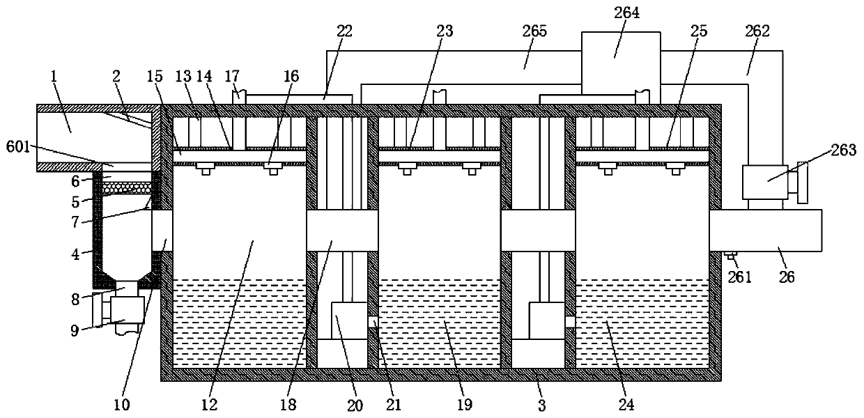
[0004] The invention provides an industrial energy-saving and environment-friendly flue gas purification device, which has the advantages of good dust filtering effect and good flue gas purification effect, and solves the problem that the existing industrial flue gas purification device usually filters the dust in the flue gas by setting a filter net , the way of filtering with filter screen is not only easy to block during use and affect the filtering effect, but also the filter screen is not easy to clean and replace, and at the same time, the dust in the flue gas is filtered through the filter screen, the filtering effect is poor, and The existing industrial flue gas purification devices cannot detect the purified flue gas, it is difficult to ensure the purification effect of the flue gas, and at the same time, it is impossible to circulate and purify the unsatisfactory flue gas, which is easy to cause pollution to the environment

Method used


Image

  • Industrial energy-saving and environment-friendly flue gas cleaning device
  • Industrial energy-saving and environment-friendly flue gas cleaning device

Examples


Embodiment Construction

[0020] The following will clearly and completely describe the technical solutions in the embodiments of the present invention with reference to the accompanying drawings in the embodiments of the present invention. Obviously, the described embodiments are only some, not all, embodiments of the present invention. Based on the embodiments of the present invention, all other embodiments obtained by persons of ordinary skill in the art without making creative efforts belong to the protection scope of the present invention.

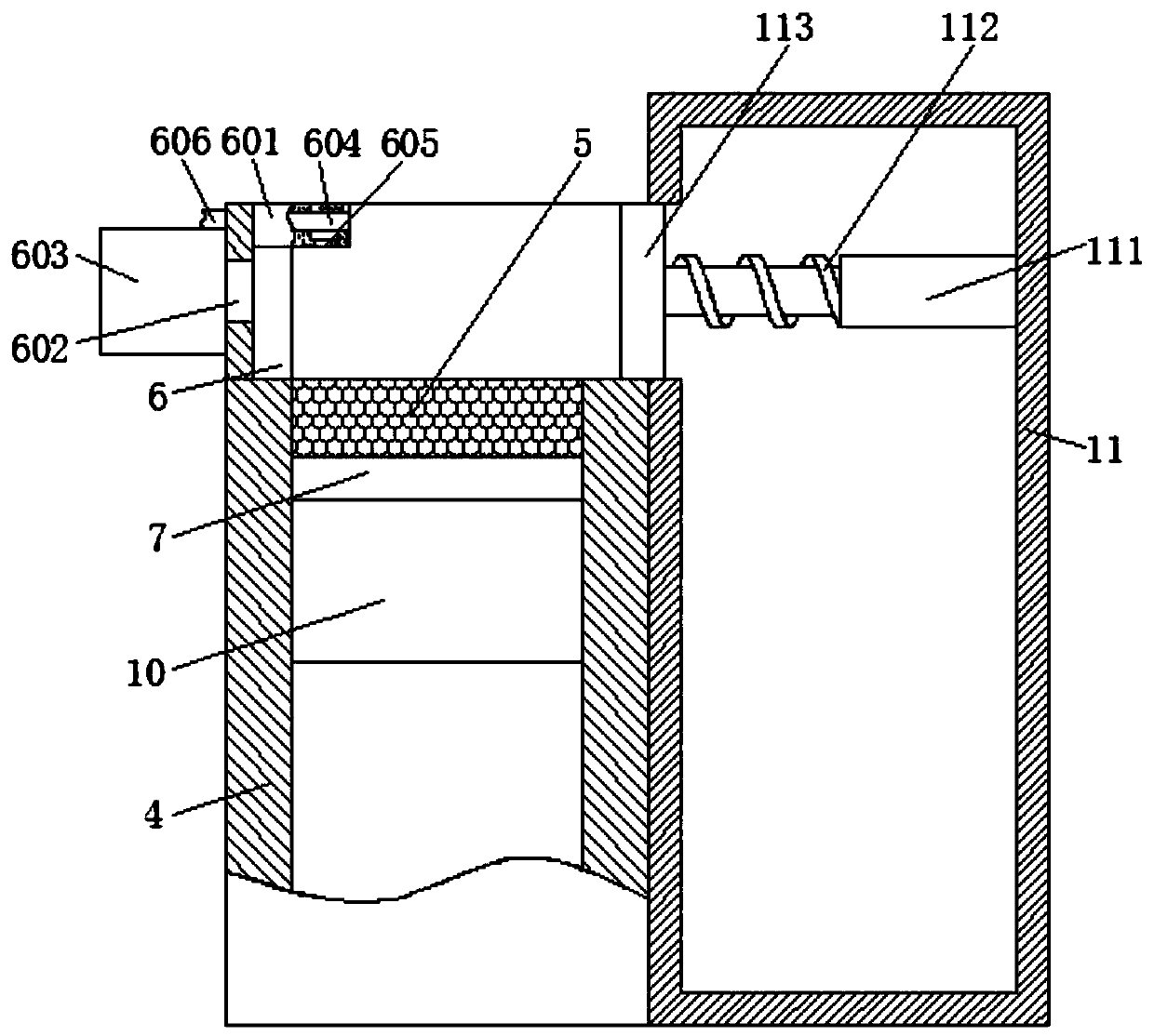
[0021] see Figure 1-2 , an industrial energy-saving and environmentally friendly flue gas purification device, including a smoke inlet pipe 1, a deflector 2 is fixedly installed on one side of the top of the inner cavity of the smoke inlet pipe 1, and a purification box 3 is provided on one side of the smoke inlet pipe 1, and the smoke inlet One side of the bottom of the tube 1 is fixedly fitted with a connecting pipe 4, and the top of the inner cavity of the...


PUM


Abstract

The invention relates to the technical field of flue gas cleaning equipment and discloses an industrial energy-saving and environment-friendly flue gas cleaning device. The industrial energy-saving and environment-friendly flue gas cleaning device comprises a flue gas feeding pipe; a guide plate is fixedly arranged on one side of the top of an inner chamber of the flue gas feeding pipe; a purifying tank is arranged on one side of the flue gas feeding pipe; a connecting pipe is fixedly sleeved on one side of the bottom of the flue gas feeding pipe; a filter screen is fixedly sleeved on the topof the inner chamber of the connecting pipe; a scraper blade located above the filter screen is moveably sleeved on one side of the inner chamber of the connecting pipe. In the industrial energy-saving and environment-friendly flue gas cleaning device, a gas concentration detection device is arranged on a flue gas discharging pipe and is used for detecting content of toxic and harmful gases in thepurified flue gas. When the effect of purifying flue gas is unsatisfactory, a second solenoid valve is opened and a fan is started to extract purified flue gas and convey into the flue gas discharging pipe, and then the purified flue gas passes by a first purifying chamber and a second purifying chamber for circular purifying treatment, so that the purifying effect of the glue gas is promoted andthe environment protection is benefited.

Description

technical field [0001] The invention relates to the technical field of flue gas purification equipment, in particular to an industrial energy-saving and environment-friendly flue gas purification device. Background technique [0002] Industrial smoke refers to the dust containing pollutants that is discharged into the atmosphere during the fuel combustion production process in the factory area, often containing various metals, non-metallic fine particles, and harmful gases of sulfur dioxide, nitrogen oxides, and hydrocarbons. The diameter of dust particles < 0.19mm is often produced by the combustion process, called "suspended particles", which are in an irregular Brownian motion state, but the particles can be enlarged through collision and condensation, which seriously pollutes the environment, affects air quality, and endangers Human health, so certain measures must be taken to control it. Commonly used dust removal devices include mechanical, filter, washing, and elec...

Claims


Application Information

Patent Timeline
IPC IPC(8): B01D50/00B01D53/78B01D53/96
Inventor 廖捷
Owner 广州众智教育咨询有限公司
Learn More