
Welding feeding mechanism with iron core positioning rod assembling and disassembling function

A positioning rod and iron core technology, which is applied in welding equipment, auxiliary welding equipment, welding/cutting auxiliary equipment, etc., can solve the unfavorable design and introduction of the automatic installation mechanism of the positioning rod of the iron core, the inability to further improve the production efficiency of the iron core, and the guide rail Reduced service life and working reliability, etc., to achieve the effect of favorable design and introduction, simple structure, simple and fast action

Pending Publication Date: 2019-06-14
KUNSHAN LIMAHE AUTOMATION SCI & TECH
View PDF1 Cites 1 Cited by
  • Summary
  • Abstract
  • Description
  • Claims
  • Application Information

AI Technical Summary

Problems solved by technology

Because the iron core slot is narrow and there are many positioning rods, even experienced workers need to spend more time (repeatedly checking the core positioning rod and iron core wire slot) for installation work, and then dismantling and operating It is cumbersome and greatly reduces the efficiency of welding operations
[0009] And it is precisely because the positioning rod is still manually installed, the current above-mentioned welding and feeding mechanism cannot be well connected with many front-end automatic equipment that uses manipulators to transport and place the iron core, resulting in the overall production efficiency of the iron core cannot be further improved
[0010] 2) It is necessary to install guide rails and sliding platforms, and the structure is complex, which is not conducive to the design and introduction of the automatic installation mechanism of the iron core positioning rod
In addition, the impact of the iron core on the guide rail is relatively large during stamping, which greatly reduces the service life and reliability of the guide rail. Although a floating sliding carrier is designed to solve this problem, it still has a relatively large impact on the material and structural strength of the guide rail. High requirements, and make the feeding mechanism more complicated as a whole, greatly increasing the manufacturing cost

Method used


Image

  • Welding feeding mechanism with iron core positioning rod assembling and disassembling function
  • Welding feeding mechanism with iron core positioning rod assembling and disassembling function
  • Welding feeding mechanism with iron core positioning rod assembling and disassembling function

Examples


Embodiment

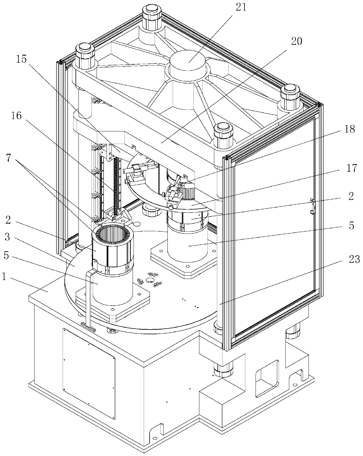
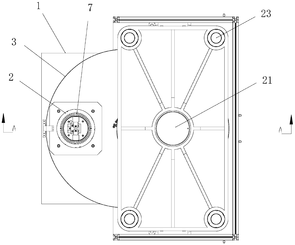
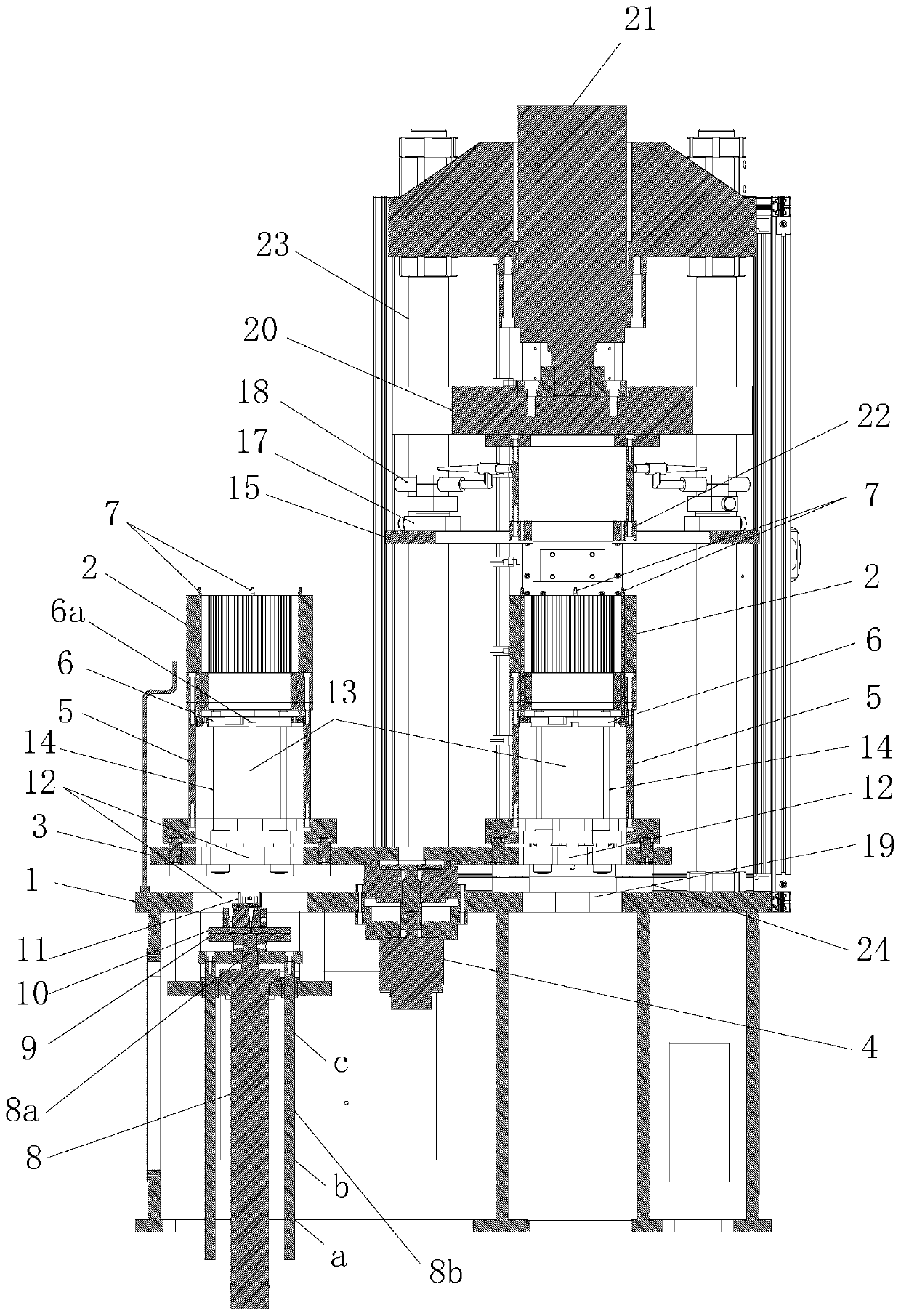
[0041] Embodiment: combine below Figure 1~Figure 3 The specific implementation of the welding feeding mechanism with the function of loading and unloading the iron core positioning rod provided by the present invention is described as follows. Such as Figure 1~Figure 3 It is the welding machine complete machine of the present invention that has been installed. Like the conventional technology, it has a workbench 1 with a welding station, a welding mechanism and a sheet arrangement mechanism arranged on the workbench 1 corresponding to the welding station, and a welding mechanism located on the workbench. 1 is used to transport the feeding mechanism of the iron core 2 to the welding station. The core improvement of the present invention for the feeding mechanism is to set an indexing rotary feeding mechanism on the workbench 1, and correspondingly design the automatic positioning of the iron core positioning rod. Loading and unloading mechanism.

[0042] combine Figure 1~...


PUM


Abstract

The invention discloses a welding feeding mechanism with an iron core positioning rod assembling and disassembling function. The mechanism is provided with an indexing rotary feeding mechanism on a workbench, a rotating disc is adopted for switching welding stations and feeding stations through rotation so as to convey an iron core, and an iron core supporting cylinder used for containing the ironcore is arranged on the rotating disc; and meanwhile, an iron core positioning rod automatic assembling and disassembling mechanism is correspondingly designed, the mechanism adopts a positioning rodlifting driving mechanism arranged at the bottom of the workbench corresponding to the feeding station for driving a positioning rod base in the iron core supporting cylinder and and a plurality of iron core positioning rods which are vertically fixed on the positioning rod base to move up and down, so that the function of the iron core positioning rods going in and out of iron core wire groovesis realized. When the iron core positioning rods are inserted into the iron core wire grooves, a magnet used for adsorbing to the bottom of the iron core is arranged on the positioning rod base. According to the mechanism, the iron core positioning rods can be automatically assembled and disassembled in the feeding process, the automation degree is higher, and therefore the production efficiency of iron core welding is remarkably improved.

Description

technical field [0001] The invention relates to a welding feeding mechanism with the function of loading and unloading iron core positioning rods. Background technique [0002] As we all know, in the known motor manufacturing industry, the stator core is manufactured by lamination of silicon steel sheets and then welded and fixed. The function of welding after lamination is to reduce the hysteresis loss and eddy current loss of the motor, and prevent The overheating of the motor will reduce its performance or even burn it out. For the welding of the iron core, many manufacturers currently use special welding equipment purchased or designed by themselves. The composition of this welding equipment usually includes a workbench, an iron core positioning tool set on the workbench, a feeding mechanism, a welding torch and a driving mechanism for driving the movement of the welding torch. [0003] Compared with manual work, the efficiency and precision of welding with welding equ...

Claims


Application Information

Patent Timeline
Patent Type & Authority Applications(China)
IPC IPC(8): B23K37/00
Inventor 李建安
Owner KUNSHAN LIMAHE AUTOMATION SCI & TECH
Learn More