Magnetic-resistance inertial sensor chip

An inertial sensor and magnetoresistance technology, applied in the field of magnetic sensors, can solve the problems of limited performance adjustment, reduced measurement linear range, low overall yield, etc., to improve the output signal strength and frequency response, high sensitivity and high frequency effect of loudness

Pending Publication Date: 2019-06-14
MULTIDIMENSION TECH CO LTD
View PDF7 Cites 9 Cited by
  • Summary
  • Abstract
  • Description
  • Claims
  • Application Information

AI Technical Summary

Problems solved by technology

However, in the measurement of inertial parameters, the excitation structure and magnetoresistive elements belong to different planes of space. In addition to the advantages of simplifying some production processes, the overall yield rate is not high, the linear range of measurement is reduced, and the mechanical transmission structure, excitation The structure and the adjustment of the relative spatial position of the magnetoresistive element are limited, which in turn leads to many shortcomings such as the limitation of performance adjustment

Method used


Image

  • Magnetic-resistance inertial sensor chip
  • Magnetic-resistance inertial sensor chip
  • Magnetic-resistance inertial sensor chip

Examples


Embodiment Construction

[0048] The present invention will be described in detail below in conjunction with specific embodiments. The following examples will help those skilled in the art to further understand the present invention, but do not limit the present invention in any form. It should be noted that those skilled in the art can make several changes and improvements without departing from the concept of the present invention. These all belong to the protection scope of the present invention.

[0049] In describing the present invention, it is to be understood that the terms "radial", "axial", "upper", "lower", "top", "bottom", "inner", "outer" etc. indicate orientation Or the positional relationship is based on the orientation or positional relationship shown in the drawings, which is only for the convenience of describing the present invention and simplifying the description, and does not indicate or imply that the referred device or element must have a specific orientation, be constructed an...


PUM


Abstract

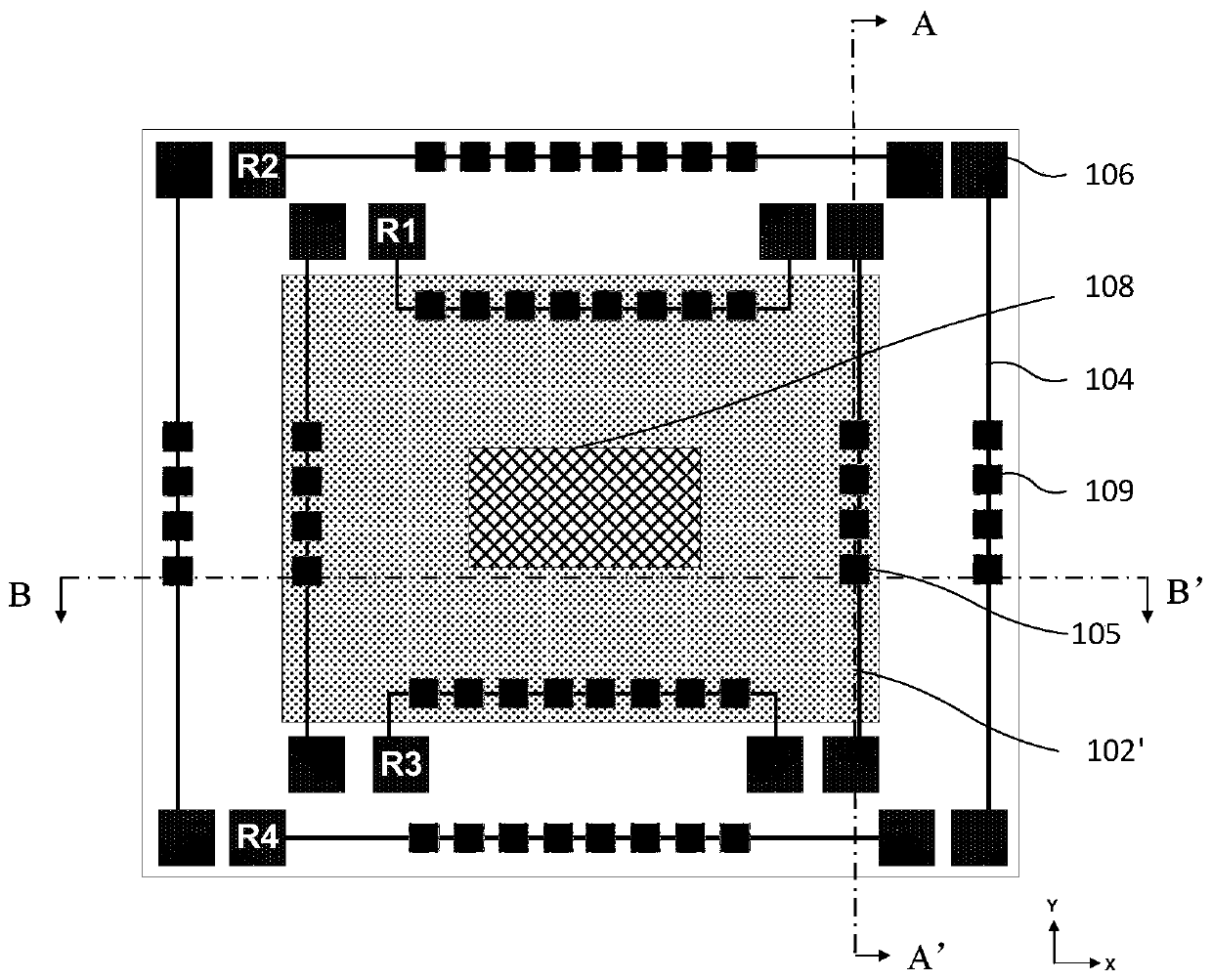
The invention discloses a magnetic-resistance inertial sensor chip. The magnetic-resistance inertial sensor chip comprises a substrate, a vibrating diaphragm, a sensing magnetic resistor and at leastone permanent magnetic film, wherein the vibrating diaphragm covers one side surface of the substrate; the sensing magnetic resistor and the permanent magnetic films are arranged on the surface, awayfrom the substrate, of the vibrating diaphragm; a contact electrode is also arranged on the surface, away from the substrate, of the vibrating diaphragm; the sensing magnetic resistor is connected with the contact electrode through a connecting wire; the substrate comprises a hollow cavity which is formed through etching; and one of the sensing magnetic resistor and the permanent magnetic films orthe whole of the sensing magnetic resistor and the permanent magnetic films can be arranged in a vertical protection area of the hollow cavity in the vibrating diaphragm. A magnetic field produced bythe permanent magnetic films of the magnetic-resistance inertial sensor chip disclosed by the invention has changed vectors in the direction of the sensitivity of the sensing magnetic resistor, so that a resistance value of the sensing magnetic resistor is changed, so that change of output electric signals is caused. According to the magnetic-resistance inertial sensor chip disclosed by the invention, the high sensitivity and the high-frequency response property of the magnetic resistor are utilized, so that the intensity of the output signal and the frequency response are improved, and detection of faint pressure, vibration or acceleration and high-frequency vibration are facilitated.

Description

technical field [0001] The invention relates to the field of magnetic sensors, in particular to a magnetoresistance inertial sensor chip. Background technique [0002] In recent years, inertial sensor chips for measuring acceleration, vibration, and pressure have attracted widespread attention in various fields. Among them, the vibration sensor field can be subdivided into solid vibration detection, including building vibration and mechanical vibration; liquid vibration detection, including hydroacoustic sonar; and gas vibration, including microphone applications and other fields. The existing inertial sensor chips are mainly based on the principles of silicon-based capacitive type, piezoelectric type, silicon-based piezoresistive type, etc., which convert acceleration, vibration, pressure and other mechanical and physical quantities into voltage or current signals for measurement. Among them, the silicon-based capacitive type has good temperature stability, high sensitivit...

Claims


Application Information

Patent Timeline
Patent Type & Authority Applications(China)
IPC IPC(8): G01D5/16
CPCG01P15/105G01H11/02G01P15/12G01R33/09G01R33/038G01R33/0076G01D5/16
Inventor 祁彬丰立贤郭海平沈卫锋薛松生
Owner MULTIDIMENSION TECH CO LTD
Why Eureka
Try Eureka