Multi-axis solid state accelerometer

a solid-state accelerometer, multi-axis technology, applied in the direction of speed/acceleration/shock measurement, measurement devices, instruments, etc., can solve the problem of limiting the sensitivity of the accelerometer, and achieve the effect of reducing manufacturing costs, increasing yields, and easy manufacturing processes

Inactive Publication Date: 2006-01-03
MIN OF NAT DEFENSE
View PDF7 Cites 65 Cited by
  • Summary
  • Abstract
  • Description
  • Claims
  • Application Information

AI Technical Summary

Benefits of technology

[0008]In accordance with an aspect of the present invention, there is provided an capacitive type multi-axis solid-state accelerometer which involves easy manufacturing process, no high aspect ratio required, increasing the yield-rate and reducing the manufacturing cost.

Problems solved by technology

This limits the sensitivity of the accelerometer.

Method used


Image

  • Multi-axis solid state accelerometer
  • Multi-axis solid state accelerometer
  • Multi-axis solid state accelerometer

Examples


first embodiment

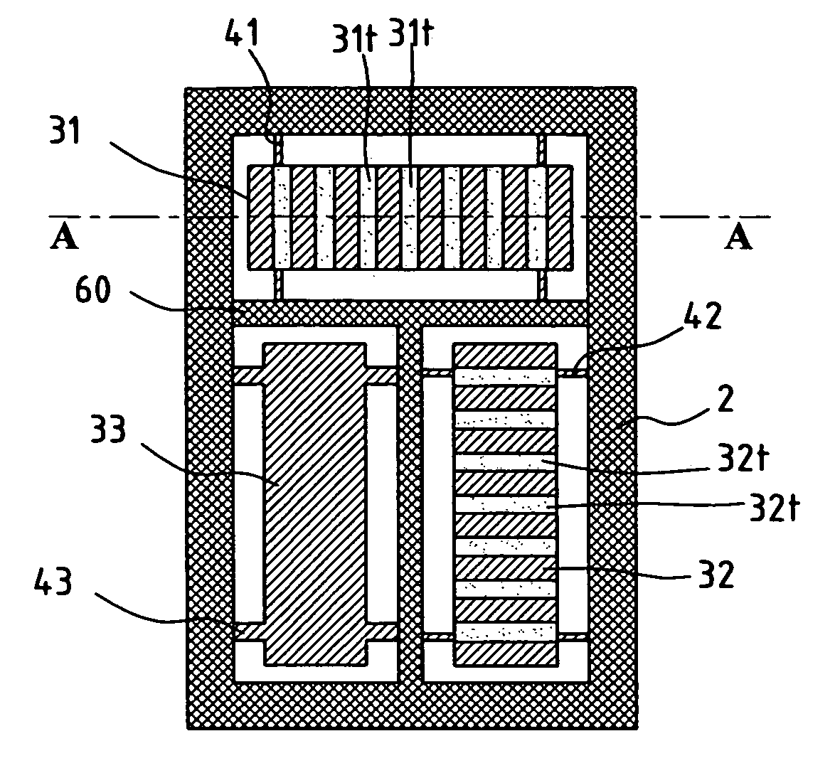
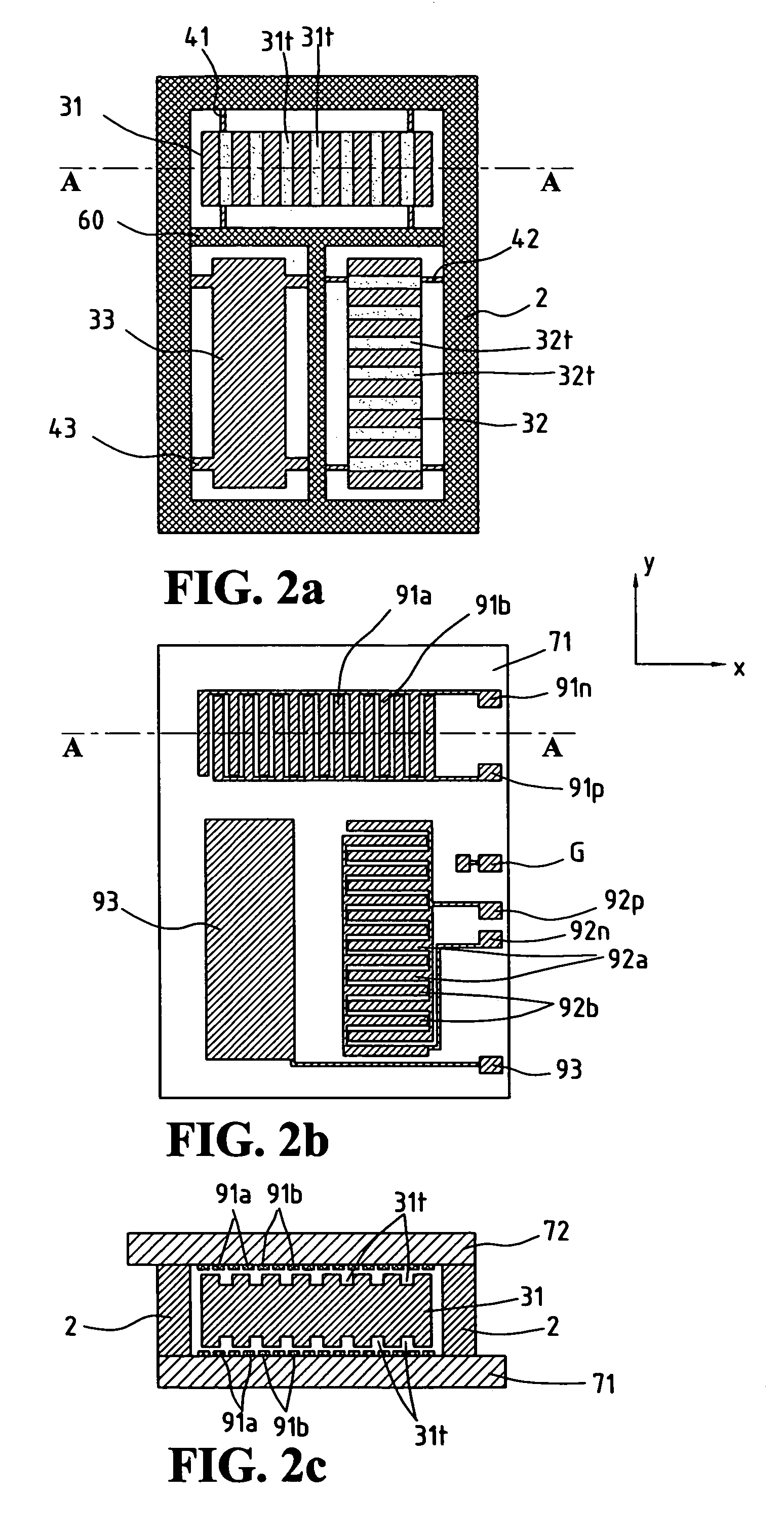
[0017]FIG. 2 shows the three-axis accelerometer in accordance with the present invention wherein FIG. 2a shows a top view of the main structure and includes three proof masses 31, 32, 33 made of electricity conductive material. The three proof masses 31, 32, 33 are connected to a frame 2 or fixing anchors 60 by sensing beams 41, 42, 43. The frame 2 or the anchors 60 are fixed to boards 71, 72. The sensing beams 41, 42, 43 make the proof masses 31, 32, 33 movable only along a first axis, a second axis parallel the boards and z-axis which is perpendicular to the boards. The proof masses 31, 32 each have grooves 31t and 32t that are perpendicular to the first axis and the second axis.

[0018]As shown in FIG. 2b, two sets of interposed stripe electrodes 91a and 91b parallel to the grooves 31t are located corresponding to the grooves 31t on the board 71, 72 and electrically connected to bond pads 91p and 91n, respectively, so as to form a first axis detection capacitors c91p and c91n with ...

second embodiment

[0022]FIG. 3 shows the three-axis accelerometer. FIG. 3a shows a top view of the main structure made of electricity conductive material and includes three proof masses 31, 32, 33. The two proof masses 31, 32 are connected with each other and located around the proof mass 33 so as to form a proof mass 312. The proof mass 33 is connected to the proof mass 312 by flexible sensing beams 43, and the proof mass 312 is connected to the sensing beam 42 by sensing beams 41. Two ends of the sensing beam 42 are connected to a frame 2 or anchors 60. The frame 2 or the anchors 60 are fixed to boards 71 and 72. The sensing beam 43 makes the proof mass 33 movable only along the z-axis perpendicular to the surface of the boards. The sensing beams 41, 42 make the proof mass 312 movable along the first axis and the second axis parallel to the boards. The proof masses 31, 32 include elongate grooves 31t and 32t perpendicular to the first axis and the second axis.

[0023]As shown in FIG. 3b, two sets of ...

third embodiment

[0030]The main structure of the three-axis accelerometer is shown in FIG. 4, and includes a proof mass 3 that is connected to the sensing beam 42 by flexible sensing beams 41. The other end of the sensing beam 42 is connected to the frame 2 or the anchor 60. The frame 2 or the anchors 60 are fixed to the boards 71, 72. The sensing beams 41 and 42 form an L-shaped sensing beam so as to allow the proof mass 3 to be movable along the first axis, the second axis and movable along the z-axis. The proof mass 3 includes a plurality of grooves 31t, 32t that are perpendicular to the first axis and the second axis, respectively, and an area that has no groove defined therein.

[0031]The electrodes on the boards 71 and 72 are similar to those described in the second embodiment, as shown in FIG. 3b. The principle of acceleration detection on each axis is the same as described above. The acceleration along the first axis does not affect the capacitors c92p, c92n on the second axis and the capacito...


PUM


Abstract

A multi-axis solid state accelerometer is made of electricity conductive material and is made by way of micro-machining. The main structure includes at least one proof mass connected to an anchor by several sensing beams and two boards are located on two sides of the main structure and fixed to the anchor. The sensing beams make the proof mass movable in parallel to or perpendicular to the boards. The surfaces of the proof mass include several grooves, which are parallel to the first axis and the second axis, and an area that has no grooves. Each board that face the grooves include two sets of electrodes and each of which includes several elongate electrodes located corresponding to the grooves. The two sets of elongate electrodes are located interposed each other. The board facing the area having no grooves has electrodes. The electrodes and the surfaces of the proof mass form detection capacitors for each axis. The component of the acceleration on each axis drives the proof mass to move along the respective axis and the capacitances of the corresponding capacitors are changed.

Description

FIELD OF THE INVENTION[0001]The present invention relates to an electrical capacity solid state accelerometer made by micro-machining techniques and more particularly, to an accelerometer for detection of acceleration in two or more axes.BACKGROUND OF THE INVENTION[0002]A conventional three-axis solid state accelerometer is shown in FIG. 1 of the attached drawings, comprising a proof mass 32, a plurality of sensing beams 42 connecting the proof mass 32 to a proof mass 31 surrounding the proof mass 32. The proof mass 32 is only moveable along y-axis. Electrodes 52p and 52n are located on opposite sides of the proof mass 32 and parallel to x-axis so as to form two y-axis sensing capacitors c92p and c92n. A plurality of sensing beams 41 connects the proof mass 31 to a proof mass 33 surrounding the proof mass 31 so that the proof mass 31 is only moveable along the x-axis. Electrodes 51p and 51n are located on two sides of the proof mass 31 and parallel to the y-axis so as to form two x-...

Claims


Application Information

Patent Timeline
Patent Type & Authority Patents(United States)
IPC IPC(8): G01P15/125G01P15/18
CPCG01P15/18G01P15/125G01P2015/082
Inventor CHEN, SHYU-MOUHUANG, MING-CHUNKAU, CHUNG-TA
Owner MIN OF NAT DEFENSE
Why Eureka
Try Eureka