

Inorganic fiber sheet, honeycomb molded body and honeycomb filter
An inorganic fiber, honeycomb-type technology, applied in the direction of inorganic chemistry, synthetic cellulose/non-cellulose material pulp/paper, fiber raw material processing, etc., can solve the problem of light weight or thinning, and difficulty in obtaining strength of bio-soluble ceramic fibers, etc. Problems, excellent processability and sufficient strength
- Summary
- Abstract
- Description
- Claims
- Application Information
AI Technical Summary
Problems solved by technology
Method used
Image

Examples
Embodiment
[0101] Hereinafter, although an Example and a comparative example demonstrate this invention more concretely, this invention is not limited to a following example.
[0102]
[0103] (base weigh)
[0104] The obtained inorganic fiber sheet was measured based on JIS P8124.
[0105] (thickness)
[0106] The obtained inorganic fiber sheet was measured based on JIS P8118.
[0107] (Tensile Strength)
[0108] The obtained inorganic fiber sheet was measured by a method according to JIS P 8113 using a Tensilon type tensile tester (manufactured by ORIENTEC).
[0109] (bending resistance)
[0110] The obtained inorganic fiber sheet was measured by the method based on ISO2493 using the bending strength tester (BENDING RESISTANCE TESTER) (made by L&W company).
[0111] (folding times)
[0112] For the obtained inorganic fiber sheet, according to the JIS P 8115 flexural strength test method, the MIT (Massachusetts Institute of Technology, MIT) testing machine was used to calculate ...
Embodiment 2
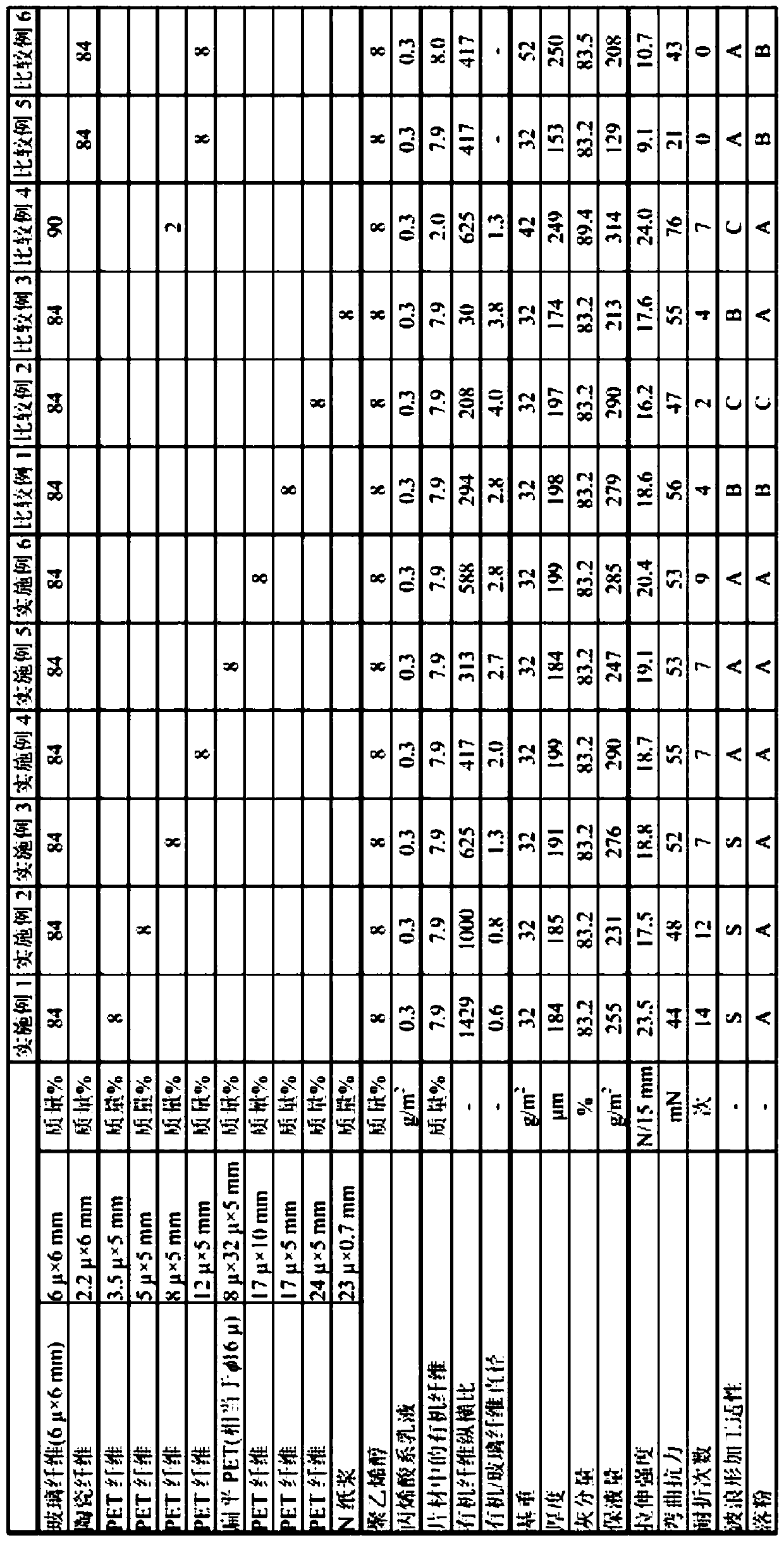
[0134] The organic fibers were changed to polyethylene terephthalate fibers (diameter: 5 μm, length: 5 mm, aspect ratio: 1000), and the basis weight, thick inorganic fiber sheet.
[0135] Thereafter, measurement and evaluation were performed in the same manner as in Example 1. The results are shown in Table 1.
Embodiment 3
[0137] The organic fibers were changed to polyethylene terephthalate fibers (diameter: 8 μm, length: 5 mm, aspect ratio: 625), and the basis weight, thick inorganic fiber sheet.
[0138] Thereafter, measurement and evaluation were performed in the same manner as in Example 1. The results are shown in Table 1.
PUM
| Property | Measurement | Unit |
|---|---|---|
| length | aaaaa | aaaaa |
| diameter | aaaaa | aaaaa |
| length | aaaaa | aaaaa |
Abstract
Description
Claims
Application Information