Power electronics unit having separating element decoupling high-voltage side from low-voltage side

A technology for power electronic devices and components, used in electrical components, magnetic/electric field shielding, printed circuit board sockets, etc.

Active Publication Date: 2019-06-14
SCHAEFFLER TECH AG & CO KG
View PDF11 Cites 0 Cited by
  • Summary
  • Abstract
  • Description
  • Claims
  • Application Information

AI Technical Summary

Problems solved by technology

[0004] However, the problem arises in these known embodiments that the two different voltage spaces, namely the high-voltage space area

Method used


Image

  • Power electronics unit having separating element decoupling high-voltage side from low-voltage side
  • Power electronics unit having separating element decoupling high-voltage side from low-voltage side
  • Power electronics unit having separating element decoupling high-voltage side from low-voltage side

Examples


Embodiment Construction

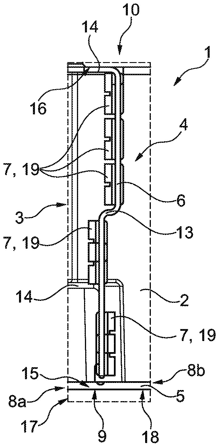
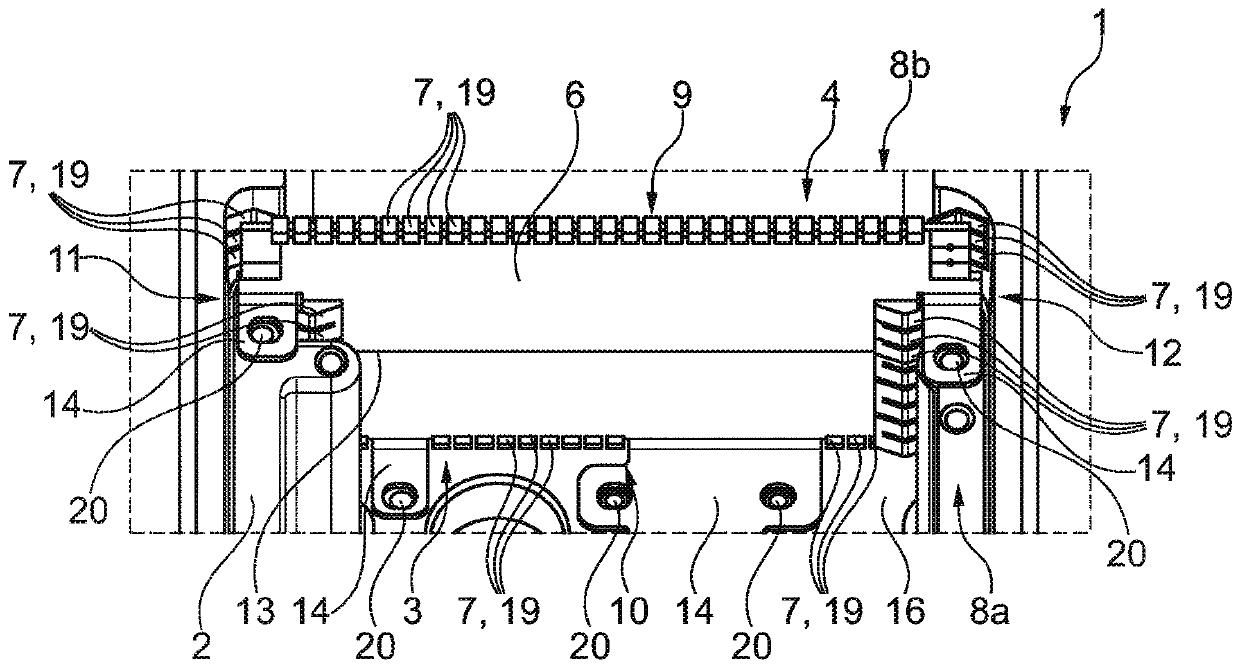
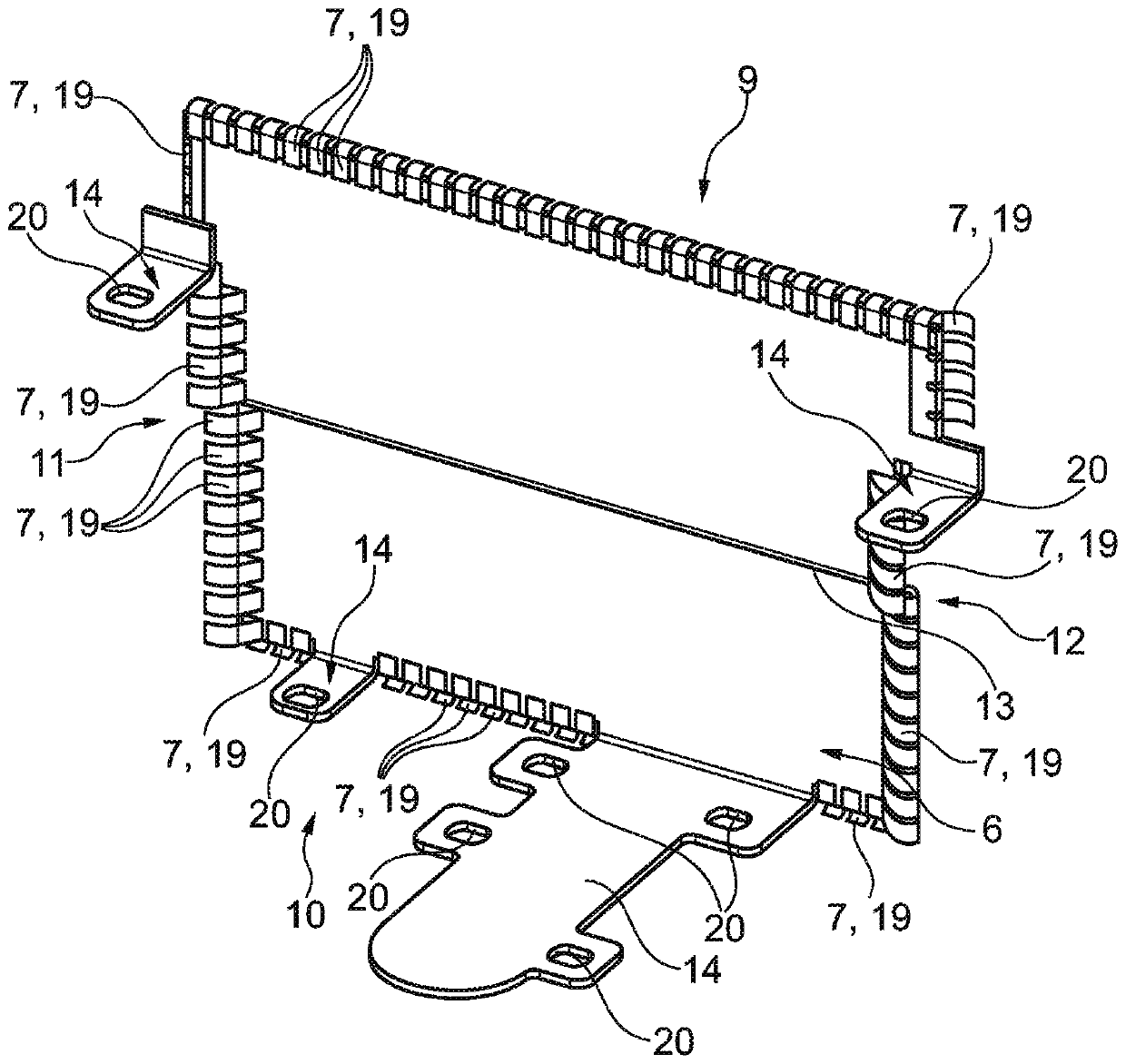
[0028] exist figure 1 The power electronics unit 1 according to a preferred exemplary embodiment can be seen in the figure under the principle structure of the power electronics unit. During operation, the power electronics unit 1 is preferably installed in a hybrid system of a hybrid drive train of a motor vehicle, which is designed as a hybrid module. The power electronics unit 1 is preferably a component of an electric drive of a hybrid system, which also has an electric motor. The power electronics unit 1 is used to supply electrical energy to the electric motor of the hybrid module or to extract electrical energy from the electric motor.

[0029] The power electronics unit 1 has a housing 2 , in which, in turn, the power electronics, which are not fully shown here for the sake of clarity, are arranged. The housing 2 basically accommodates a plurality of electronic components that are assembled into a power electronics unit. exist figure 1 The circuit board 5 of this p...


PUM


Abstract

The invention relates to a power electronics unit (1) having an electrically conductive housing (2) in which a low-voltage space region (3) and a high-voltage space region (4) are formed, and a printed circuit board (5), some sections of which project into the low-voltage space region (3) and into the high-voltage space region (4), wherein a separating element (6) is arranged in the housing (2) and makes contact with the housing (2) and/or the printed circuit board (5) by means of contact spring sections (7) provided on the separating element such that the space regions (3, 4) are electromagnetically decoupled from each other. The invention also relates to an electrical drive system for a motor vehicle, having the power electronics unit (1).

Description

technical field [0001] The invention relates to a power electronics unit (also referred to simply as power electronics), in particular for a hybrid drive train of a motor vehicle, which has a conductive / current-carrying housing and a printed circuit board, A low-voltage space region and a high-voltage space region are formed in the housing, into which the printed circuit board protrudes or is arranged in sections. Furthermore, the invention relates to an electric drive system for a motor vehicle, in particular for a drive train of a motor vehicle, such as a hybrid system (for example in the form of a hybrid module), an electric axle (E-Achse) or In a similar embodiment, the electric drive system has an electric motor and a power electronics unit electrically connected to the electric motor. Background technique [0002] A less relevant prior art is known from DE 10 2015 201 314 A1. This document discloses power electronics in the actuator. [0003] It is also known that d...

Claims


Application Information

Patent Timeline
IPC IPC(8): H05K7/14H05K9/00
CPCH05K9/0037H05K7/14329
Inventor 塞德里克·布莱斯斯特凡·普赖辛丹尼尔·埃克施泰因于尔根·蒂佩尔尼古拉·格拉曼
Owner SCHAEFFLER TECH AG & CO KG
Why Eureka
Try Eureka