
Artificial chordal implantation system with gripping aid

A technology of artificial chordae and auxiliary devices, which is applied in the artificial chordae implantation system and the field of devices for repairing heart valve defects. To achieve the effect of reducing the range of activity

Active Publication Date: 2020-11-24
HANGZHOU VALGEN MEDTECH CO LTD
View PDF7 Cites 0 Cited by
  • Summary
  • Abstract
  • Description
  • Claims
  • Application Information

AI Technical Summary

Problems solved by technology

However, because the valve leaflet is always in a pulsating state, and the surface of the valve leaflet is smooth tissue, it is difficult for the clamping device to quickly and successfully clamp the valve leaflet. Even if the valve leaflet is clamped, the valve leaflet may fall off from the clamping device. Prolonged operation time and even failed operation
Moreover, after the valve leaflets are captured, if the clamping position is found to be unsatisfactory, the operator needs to fine-tune the clamping device. At this time, the valve leaflets are easily slipped from the clamping device, resulting in prolonged operation time or even surgical failure.

Method used


Image

  • Artificial chordal implantation system with gripping aid
  • Artificial chordal implantation system with gripping aid
  • Artificial chordal implantation system with gripping aid

Examples


Embodiment 1

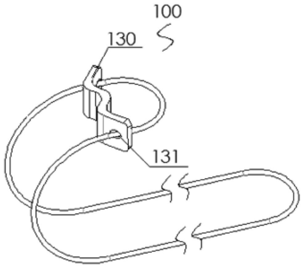
[0047] like Figure 3-24 As shown, the artificial chord tendon implantation system with a clamping auxiliary device is used to implant the artificial chord tendon 100 into the patient's body to replace the diseased or broken chord tendon in the patient's heart. The artificial chord implantation system includes a clamping device 300 , a puncture device 400 , a pushing device 200 and a clamping auxiliary device 500 . The pushing device 200 includes a pushing catheter 210 . The clamping device 300 includes a clamping push rod 330 accommodating the artificial chordae 100 , and a distal clamp 310 and a proximal clamp 320 for cooperating to clamp the leaflet. The puncture device 400 includes a puncture push rod 420 and a puncture needle 410 disposed at a distal end of the puncture push rod 420 . The clamping push rod 330 and the puncture push rod 420 are respectively movably installed in the pushing catheter 210 . Piercing needle 410 has a tapered distal end and a hooked body. The...

Embodiment 2

[0083] The artificial chord implantation system of this embodiment is basically the same in structure as the artificial chord implantation system of Embodiment 1, the difference is that in this embodiment, the clamping auxiliary part 510 is a deformed structure composed of multiple support rods. The structure, the deformed structure is housed in the pushing catheter 210 together with the clamping auxiliary arm 520 after contraction and deformation.

[0084]Specifically, the deformed structure is an open bifurcated structure or an umbrella-shaped structure composed of a plurality of support rods. The clamping auxiliary part 510 has a compressed state and a stretched state in the natural state. In the compressed state, the clamping auxiliary part 510 can be pushed in the auxiliary arm receiving cavity 250 of the pushing conduit 210; After stretching out, it turns into an extended state, which can support the lower surface of the valve leaflet, stabilize the valve leaflet, and fa...

Embodiment 3

[0090] The structure of the artificial chord implantation system of this embodiment is basically the same as that of the second embodiment, the difference is that in this embodiment, the clamping auxiliary member 510 located It is a closed structure composed of multiple support rods, and the closed structure can be circular, rhombus, oval, pear-shaped, polygonal or other irregular shapes that can form a closed structure, such as Figures 27a-27c shown. like Figure 28a and Figure 28b As shown, after the clamping aid 510 protrudes from the distal end of the pushing catheter 210 , the contact area between it and the leaflet 600 is larger, and the support for the leaflet 600 is better.

[0091] It can be understood that, in other embodiments, at least one flexible and / or elastic connecting rod 511 can be arranged between the support rods of the closed structure to improve the self-stability of the closed structure and further enhance the clamping aid 510 support for the leafl...


PUM


Abstract

The invention discloses an artificial chordae implanting system with a clamping auxiliary device. The artificial chordae implanting system comprises a pushing catheter, a clamping device, a puncturingdevice and the clamping auxiliary device; the clamping device comprising a clamping push rod containing artificial chordae, and further comprises a far-end chuck and a near-end chuck which are used for being matched to clamp a valve leaflet; the puncturing device comprises puncturing push rods and puncturing syringe needles arranged at the far ends of the puncturing push rods; the clamping push rod and the puncturing push rods are movably mounted in the pushing catheter in a penetrating mode, and the puncturing syringe needles are provided with conical far ends and hook-shaped bodies; and theclamping auxiliary device comprises a clamping auxiliary arm movably mounted in the pushing catheter in a penetrating mode, and a clamping auxiliary piece arranged at the far end of the clamping auxiliary arm, and the clamping auxiliary arm pushes the clamping auxiliary piece to stretch out from the far end of the artificial chordae implanting system and then is matched with the clamping device to clamp the valve leaflet. According to the artificial chordae implanting system, the clamping auxiliary piece can be supported on the lower surface of the valve leaflet to assist the clamping devicein stabilizing the pulsating valve leaflet, the clamping stability is improved, and the valve leaflet is prevented from slipping away from the clamping device.

Description

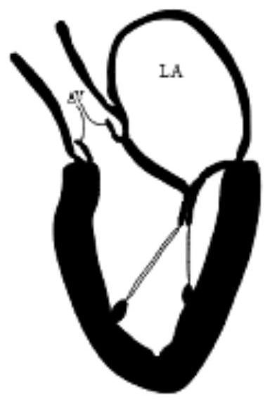
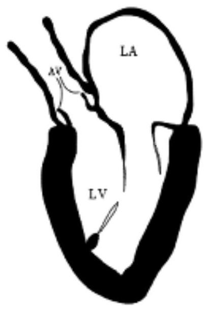
technical field [0001] The invention belongs to the technical field of medical devices, and relates to a device for repairing heart valve defects, in particular to an artificial chord implantation system. Background technique [0002] The mitral valve is a one-way "valve" between the left atrium (abbreviation: LA) and the left ventricle (abbreviation: LV), which can ensure blood flow from the left atrium to the left ventricle. See figure 1 , a normal healthy mitral valve has multiple chordae. The leaflets of the mitral valve are divided into anterior leaflet and posterior leaflet. When the left ventricle is in a diastolic state, the two are in an open state, and blood flows from the left atrium to the left ventricle; when the left ventricle is in a systolic state, the chordae are stretched to ensure The valve leaflets will not be rushed to the atrium side by the blood flow, and the front and rear leaflets are well closed, thereby ensuring that blood flows from the left ven...

Claims


Application Information

Patent Timeline
Patent Type & Authority Patents(China)
IPC IPC(8): A61F2/24
Inventor 潘湘斌张伟伟孟旭张庭超
Owner HANGZHOU VALGEN MEDTECH CO LTD
Learn More