
Medical cervical vertebra tractor

A cervical vertebra tractor and the technology of the tractor, which are applied in the field of medical equipment, can solve the problems of cervical vertebra tractors such as difficulty, airtightness, and low manufacturing cost, and achieve the effect of good air permeability

Inactive Publication Date: 2019-06-18
蔡碎女
View PDF5 Cites 0 Cited by
  • Summary
  • Abstract
  • Description
  • Claims
  • Application Information

AI Technical Summary

Problems solved by technology

Cervical traction can only play an auxiliary role through any drug treatment, and there are obvious defects in manual correction: first, the magnitude of the force cannot be quantified; Consequences; third, it is only a one-time effect, and its safety and effectiveness are severely limited
The structure of the existing cervical vertebra tractor is also quite simple, and the manufacturing cost is also relatively low
Although the existing cervical traction device has been approved by the medical field, it still has some shortcomings: because everyone's neck size and length are different, the size and tightness of the existing cervical traction device are not easy to adjust In the process of wearing, because the surface hardness of the tractor is too strong, it is easy to bring a certain amount of pressure to the cervical spine, which makes it difficult for some patients with cervical spine to fit; wearing the cervical tractor for a long time may easily lead to airtightness, stuffiness, etc.
In addition, since the neck of the human body is curved, it is difficult for the cervical tractor to fully contact the neck, and it is easy to leave gaps and other adverse conditions

Method used


Image

  • Medical cervical vertebra tractor
  • Medical cervical vertebra tractor

Examples


Embodiment Construction

[0016] In order to make the present invention more obvious and understandable, the detailed description is as follows in conjunction with the accompanying drawings.

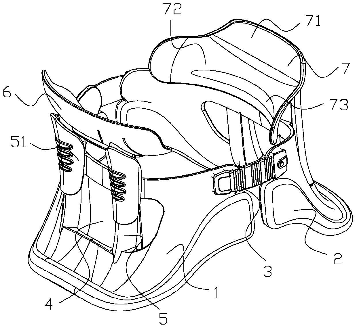
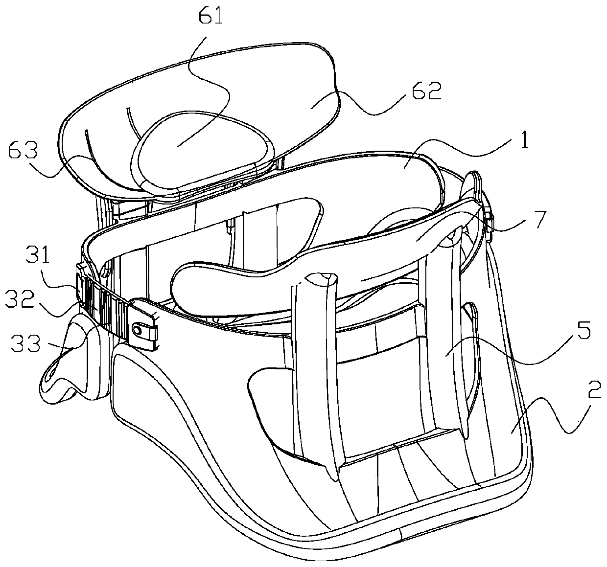
[0017] Such as figure 1 and figure 2 Shown, a kind of medical cervical vertebra tractor, this retractor comprises front cervical vertebra cover 1 and back cervical vertebra cover 2, and front cervical vertebra cover 1 and back cervical vertebra cover 2 are connected by detachable elastic mechanism 3. The elastic mechanism 3 includes an elastic buckle 31 and an elastic band 32 , the elastic band 32 is provided with a plurality of elongated adjustment grooves 33 , and the elastic buckle 31 is matched with the adjustment grooves 33 . The tightness can be easily adjusted. The front cervical spine cover 1 and the rear cervical spine cover 2 are connected to form a cylindrical body matching the neck of a human body. The width of the upper part of the cylindrical body is greater than the width of the lower part of t...


PUM


Abstract

The invention relates to the technical field of medical devices, in particular to a medical cervical vertebra tractor. The medical cervical vertebra tractor comprises a front cervical vertebra cover and a rear cervical vertebra cover which are connected through detachable tightening mechanisms; the front cervical vertebra cover and the rear cervical vertebra cover are connected to form a cylindrical body matched with the neck of a human body; through holes are formed in the middles of the front cervical vertebra cover and the rear cervical vertebra cover; support connecting rods are arranged on the front cervical vertebra cover and the rear cervical vertebra cover, the top ends of the support connecting rods on the front cervical vertebra cover are connected with a front support plate, anda jaw base plate matched with the jaw of the human body is arranged on the front support plate; a rear base plate matched with the rear side of the neck of the human body is connected to the top of the support connecting rods on the rear cervical vertebra cover. The medical cervical vertebra tractor has the benefits as follows: the tractor is better matched with the structure of the neck of the human body and is lightweight in structure; the tractor is comfortable to wear and good in contact and breathability and cannot cause stuffiness; the degree of tightness can be adjusted.

Description

technical field [0001] The invention relates to the technical field of medical instruments, in particular to a medical cervical traction device. Background technique [0002] With the aging of the population in our country and the great changes in the way of life and work, the incidence of cervical spondylosis is increasing rapidly and becoming younger. The basic link of various types, different degrees or stages of cervical spondylosis is the degeneration of the intervertebral disc, and the result of degeneration is that the intervertebral disc is prone to rupture under the action of external force. Abnormal physiological curvature is the result of mechanical disorder. Only through mechanical adjustment and normal mechanical balance can the physiological curvature be restored. This is cervical traction. Cervical traction can only play an auxiliary role through any drug treatment, and there are obvious defects in manual correction: first, the magnitude of the force cannot b...

Claims


Application Information

Patent Timeline
IPC IPC(8): A61F5/042
Inventor 蔡碎女周俊英
Owner 蔡碎女
Learn More