
Drop bottle used for ophthalmologic nursing and facilitating accurate positioning

A precise positioning and drop bottle technology, applied in ophthalmology treatment, etc., can solve the problems of increased difficulty and difficulty in accurate judgment, and achieve the effect of avoiding falling

Active Publication Date: 2019-06-18
THE FIRST AFFILIATED HOSPITAL OF HENAN UNIV OF SCI & TECH
View PDF2 Cites 3 Cited by
  • Summary
  • Abstract
  • Description
  • Claims
  • Application Information

AI Technical Summary

Problems solved by technology

However, for the elderly and children, it is difficult to accurately judge whether the straight line determined by the two points of the drip hole and the eyeball is in the vertical direction, which increases the difficulty for patients to self-administer eye drops.

Method used

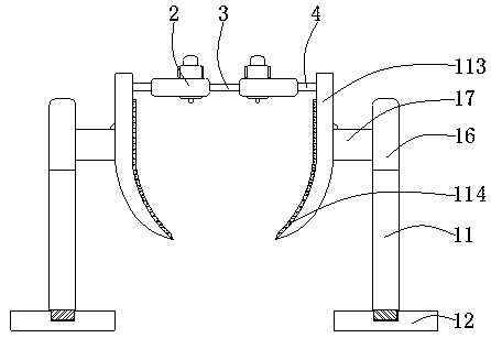

Image

  • Drop bottle used for ophthalmologic nursing and facilitating accurate positioning
  • Drop bottle used for ophthalmologic nursing and facilitating accurate positioning
  • Drop bottle used for ophthalmologic nursing and facilitating accurate positioning

Examples


Embodiment 1

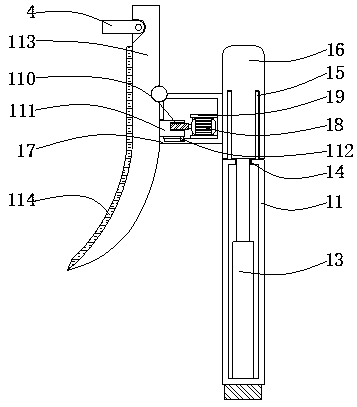
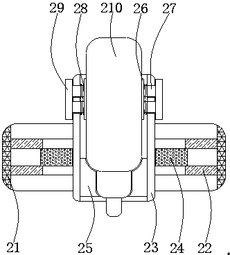
[0026] Such as Figure 1-3As shown, a drop bottle for eye care that is convenient for precise positioning includes a supporting mechanism 1, an auxiliary dripping mechanism 2, a first connecting rod 3, and a second connecting rod 4. The supporting mechanism 1 includes a supporting column 11, a matching Heavy feet 12, electric push rod 13, limit ring 14, guide rod 15, bearing column 16, support platform 17, micro motor 18, support frame 19, rotating shaft 110, moving column 111, slide block 112, support plate 113, Cushion pad 114, support column 11 is arranged in the middle of the top of counterweight foot 12, one end of the bottom of electric push rod 13 is fixedly connected in the center of the inner wall bottom of support column 11, limit ring 14 is arranged in the center of support column 11 top, guide rod The number of 15 is two, and one end of the bottom of the two guide rods 15 is symmetrically fixedly connected to the left and right sides of the top of the support colum...

Embodiment 2

[0029] On the basis of Embodiment 1, one end of the bottom of the support column 11 runs through the outer wall in the middle of the top of the counterweight foot 12 and extends to the inside of the wall of the counterweight foot 12, and the support column 11 and the wall of the counterweight foot 12 are connected by threads. One end of the bottom of the limit ring 14 runs through the outer wall at the center of the top of the support column 11 and extends to the inside of the support column 11 , and the limit ring 14 closely fits and is fixedly connected to the wall of the support column 11 .

Embodiment 3

[0031] On the basis of Embodiments 1 and 2, one end of the top of the electric push rod 13 penetrates the limit ring 14 and extends to the outside of the support column 11, the electric push rod 13 fits with the wall of the limit ring 14, and the electric push rod One end of the top of 13 is fixedly connected to the middle of the bottom of the bearing column 16, and the left and right sides of the bottom of the bearing column 16 are symmetrically provided with limiting grooves, and one end of the top of the two guide rods 15 extends to the inside of the two limiting grooves respectively and aligns with the limiting groove. The inner wall of the groove fits.


PUM


Abstract

The invention discloses a drop bottle used for ophthalmologic nursing and facilitating accurate positioning and relates to the technical field of ophthalmologic nursing. The drop bottle used for ophthalmologic nursing and facilitating accurate positioning comprises a supporting mechanism, an auxiliary dropping mechanism, a first connecting rod and a second connecting rod, the supporting mechanismcomprises a support column, a counterweight foot, an electric push rod, a limit ring, a guide rod, a bearing column, a support table, a micro motor, a support frame, a rotating shaft, a moving column,a slide block, a support plate and a buffer pad, the support column is arranged in the center of the top of the counterweight foot, one end of the bottom of the electric push rod is fixedly connectedin the center of the bottom of the inner wall of the support column, the limit ring is arranged in the center of the top of the support column. The drop bottle used for ophthalmologic nursing and facilitating accurate positioning can realize the effect of adjusting the drop direction and assist the elderly and the young to judge whether the straight line determined by a drop hole and an eyeball is vertical so as to facilitate use of eye drops for the elderly and the young.

Description

technical field [0001] The invention relates to the technical field of eye care, in particular to a drop bottle for eye care which is convenient for precise positioning. Background technique [0002] In the process of instilling eye drops, there are two necessary conditions to make the liquid medicine drip into the eyes accurately: one is that the human eye and the drop hole of the eye drop bottle must be in the right direction, and the other is that the human eye and the drop hole must be aligned. The connection line must be in the vertical direction. None of the existing eye drops bottles has the alignment function between the drip hole and the eye. Therefore, to make the liquid drop into the eye accurately, the patient usually needs to rely on others to operate. Without the help of others, the patient usually can only use Drop eye drops in a lying down or looking up position. However, for old people and children, it is difficult to accurately judge whether the straight ...

Claims


Application Information

Patent Timeline
IPC IPC(8): A61F9/00
Inventor 徐娜侯欢欢王亚靖
Owner THE FIRST AFFILIATED HOSPITAL OF HENAN UNIV OF SCI & TECH
Learn More