Easy-to-separate extraction device
An extraction device and an easy-to-separate technology, applied in the direction of liquid solution solvent extraction, etc., can solve the problems of control, inaccurate experiment, impure extract, etc., and achieve the effect of accurate discharge and avoiding residue
- Summary
- Abstract
- Description
- Claims
- Application Information
AI Technical Summary
Problems solved by technology
Method used
Image
Examples
Embodiment 1
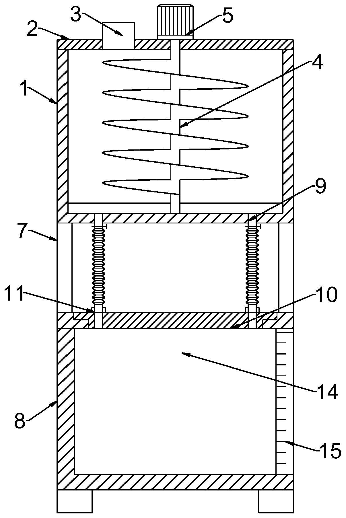
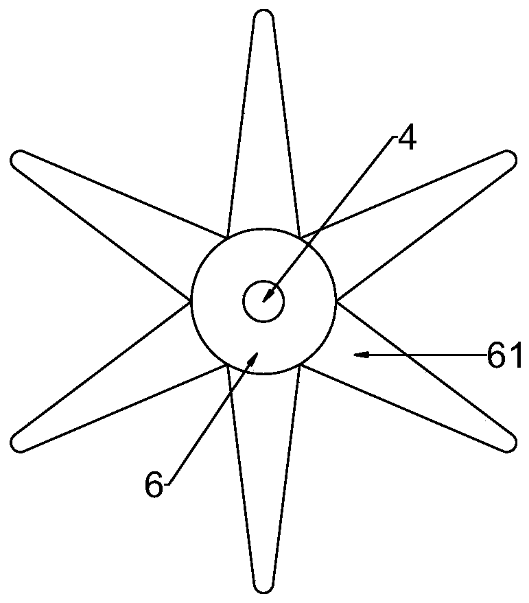
[0025] see Figure 1~2 , in the embodiment of the present invention, a kind of extraction device that is easy to separate, comprises extraction cavity 1 and precipitation cavity 8, and described extraction cavity 1 and precipitation cavity 8 are connected, and described extraction cavity 1 is provided with stirring mechanism, and described precipitation cavity A discharge structure is provided on the chamber 8, and a material guide mechanism for synchronous rotation for discharge is also connected to the stirring mechanism.
[0026] The extraction chamber 1 is fixedly connected with a first cover plate 2, and the first cover plate 2 is assembled on the upper end of the extraction chamber 1 by means of riveting or screw fitting, and the first cover plate 2 is connected with a A feed pipe 3 for introducing materials and a stirring mechanism for promoting extraction; the stirring mechanism includes a motor 5 fixedly arranged in the middle of the upper end of the first cover plate...
Embodiment 2
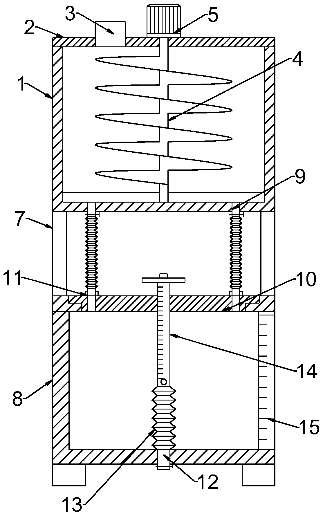
[0032] see Figure 3-5 , when the stratified solution is discharged, usually it cannot be accurately controlled, which will cause problems such as impurity of the extracted solution or low extraction efficiency. Therefore, on the basis of Example 1, in the embodiment of the present invention, an easy-to-separate In the extraction device, a discharge pipeline 12 is connected through the lower end of the precipitation chamber 8, and a valve is provided on the discharge pipeline 12, and a discharge structure is connected to the upper end of the discharge pipeline 12 through a connecting hose 13.
[0033] The discharge structure includes a sliding sleeve 14 connected to the upper end of the connecting hose 13 and a movable blocking structure located in the sliding sleeve 14; the sliding sleeve 14 slides through the middle of the second cover plate 10, so that The surface of the sliding sleeve 14 is engraved with a scale corresponding to the side of the observation window 15, so th...
PUM
 Abstract
Description
Claims
Application Information
 - R&D
- Intellectual Property
- Life Sciences
- Materials
- Tech Scout
- Unparalleled Data Quality
- Higher Quality Content
- 60% Fewer Hallucinations
Browse by: Latest US Patents, China's latest patents, Technical Efficacy Thesaurus, Application Domain, Technology Topic, Popular Technical Reports.
© 2025 PatSnap. All rights reserved.Legal|Privacy policy|Modern Slavery Act Transparency Statement|Sitemap|About US| Contact US: help@patsnap.com


