Continuous casting tube type crystallizer
A tubular crystallizer and continuous casting technology, applied in the field of metallurgical equipment, can solve the problems of increased wear of copper tubes and casting billets, shortened service life of copper tubes, increased heat transfer resistance, etc., so as to increase service life and strengthen structural strength. , the effect of reducing the amount of deformation
- Summary
- Abstract
- Description
- Claims
- Application Information
AI Technical Summary
Problems solved by technology
Method used
Image

Examples
Embodiment 1
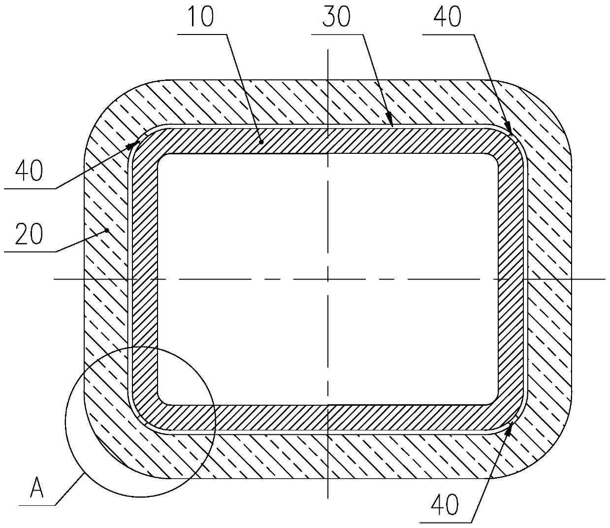
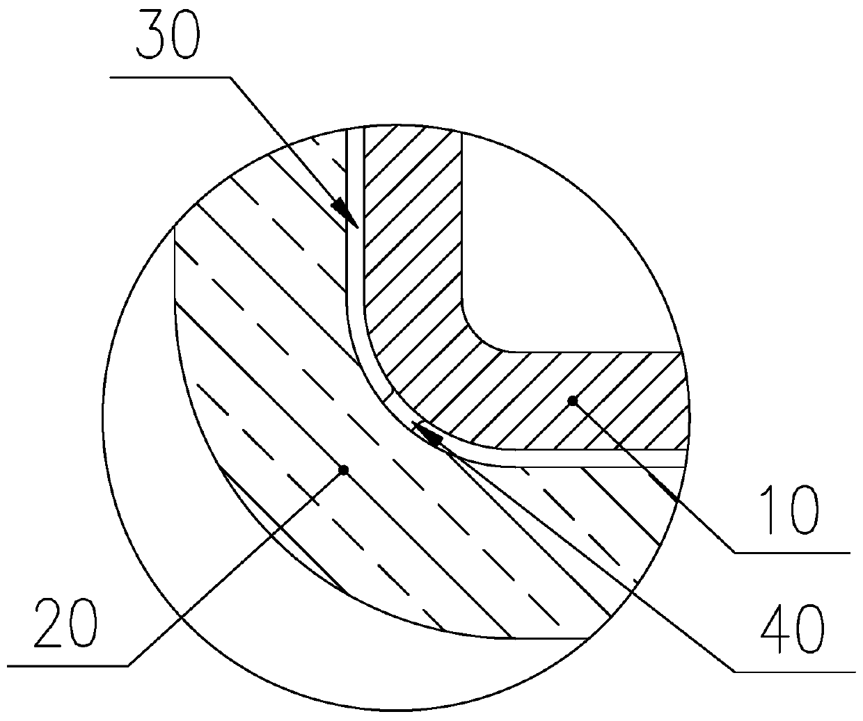
[0028] A continuous casting tube mold includes a copper tube 10, a water jacket 20, and a copper bar 40; the cross section of the copper tube 10 is a rectangle 320mm×410mm, and the adjacent sides of the copper tube 10 are smoothly connected by arcs. There are four arcs in total; the water jacket 20 is sleeved on the copper pipe 10, and a water gap 30 is formed between the water jacket 20 and the copper pipe 10; the copper strip 40 is set on the arc portion along the height direction of the copper pipe 10 On the outer surface, the outer surface of the copper strip 40 is arc-shaped and fits together with the inner surface of the water jacket 20; there are four copper strips 40 and they are located on the four arcs. The arc length is 30mm, the distance between the outer surface of the copper strip 40 and the outer surface of the copper tube 10 is 8mm, and the height of the copper strip 40 is 800mm; the top of the copper strip 40 is 50mm lower than the top of the copper tube 10, and...
Embodiment 2
[0031] A continuous casting tube mold includes a copper tube 10, a water jacket 20, and a copper bar 40; the cross section of the copper tube 10 is a rectangle 150mm×150mm, and the adjacent sides of the copper tube 10 are smoothly connected by arcs. There are four arcs in total; the water jacket 20 is sleeved on the copper pipe 10, and a water gap 30 is formed between the water jacket 20 and the copper pipe 10; the copper strip 40 is set on the arc portion along the height direction of the copper pipe 10 On the outer surface, the outer surface of the copper strip 40 is arc-shaped and fits together with the inner surface of the water jacket 20; there are four copper strips 40 and they are located on the four arcs. The arc length is 10mm, the distance between the outer surface of the copper strip 40 and the outer surface of the copper tube 10 is 5mm, and the height of the copper strip 40 is 700mm; the top of the copper strip 40 is 100mm lower than the top of the copper tube 10, an...
Embodiment 3
[0034] A continuous casting tube mold includes a copper tube 10, a water jacket 20 and a copper bar 40; the cross section of the copper tube 10 is a rectangle with a 200mm×200mm, and the adjacent sides of the copper tube 10 are smoothly connected by arcs. There are four arcs in total; the water jacket 20 is sleeved on the copper pipe 10, and a water gap 30 is formed between the water jacket 20 and the copper pipe 10; the copper strip 40 is set on the arc portion along the height direction of the copper pipe 10 On the outer surface, the outer surface of the copper strip 40 is an arc surface and fits together with the inner surface of the water jacket 20; the arc length of the outer surface of the copper strip 40 is 20 mm, and the outer surface of the copper strip 40 and the copper tube 10 The distance between the outer surfaces of the copper bars is 6mm, and the height of the copper bars 40 is 100mm; there are 12 copper bars 40 in total, and 3 copper bars 40 are spaced along the ...
PUM
| Property | Measurement | Unit |
|---|---|---|
| Height | aaaaa | aaaaa |
| Radius | aaaaa | aaaaa |
Abstract
Description
Claims
Application Information
 - Generate Ideas
- Intellectual Property
- Life Sciences
- Materials
- Tech Scout
- Unparalleled Data Quality
- Higher Quality Content
- 60% Fewer Hallucinations
Browse by: Latest US Patents, China's latest patents, Technical Efficacy Thesaurus, Application Domain, Technology Topic, Popular Technical Reports.
© 2025 PatSnap. All rights reserved.Legal|Privacy policy|Modern Slavery Act Transparency Statement|Sitemap|About US| Contact US: help@patsnap.com