Control method, device, device and storage medium for laminating equipment
A technology of laminating equipment and control method, applied in metal processing equipment, program-controlled manipulators, manufacturing tools, etc., can solve the problem that the lamination speed cannot be further improved, save lamination time, improve lamination speed, and solve the problem of lamination. slow effect
- Summary
- Abstract
- Description
- Claims
- Application Information
AI Technical Summary
Problems solved by technology
Method used
Image
Examples
Embodiment 1
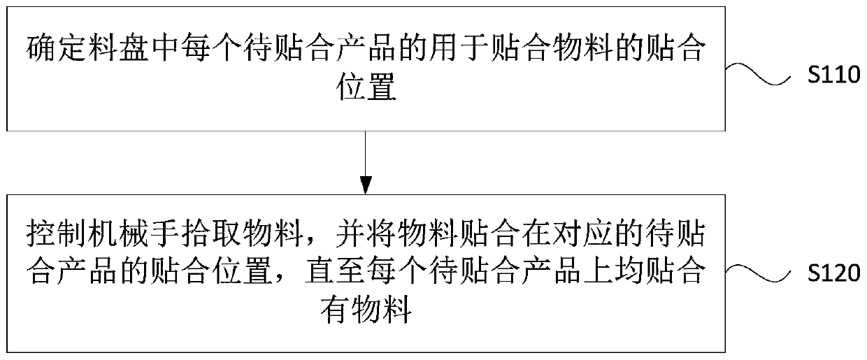
[0042] figure 1 It is a flow chart of a control method for laminating equipment provided in Embodiment 1 of the present invention. This embodiment is applicable to the situation where laminating equipment is used to bond materials to products to be bonded. This method can be implemented in the embodiment of the present invention The control device of the laminating equipment can be implemented by means of software and / or hardware, and can generally be integrated in the laminating equipment.
[0043] see figure 1 , the control method of the bonding equipment includes the following steps:
[0044] S110. Determine a bonding position for bonding materials of each product to be bonded in the tray.
[0045] Usually, the bonding equipment is equipped with a conveying device, and a plurality of products to be bonded are placed in a tray and transported to the bonding station of the bonding device through the conveying device. Multiple products to be laminated are arranged in a matr...
Embodiment 2
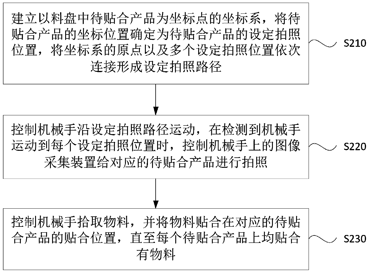
[0054] figure 2 It is a flow chart of a control method for laminating equipment provided by Embodiment 2 of the present invention. This embodiment is embodied on the basis of the above-mentioned embodiment. This embodiment has the same inventive concept as the above-mentioned embodiment. The explanation of the same or corresponding terms will not be repeated in this embodiment.
[0055] see figure 2 , the control method of the bonding equipment includes the following steps:
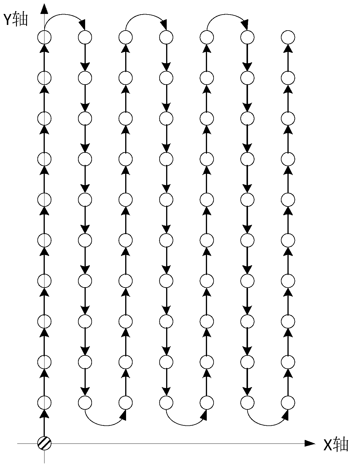
[0056] S210. Establish a coordinate system with the product to be bonded in the tray as the coordinate point, determine the coordinate position of the product to be bonded as the set photo position of the product to be bonded, and set the origin of the coordinate system and multiple set photo positions Connect in sequence to form a set photo path.
[0057] Specifically, the product to be bonded has a certain shape, and the coordinates of a point on it (such as the geometric center) can be regarded as...
Embodiment 3
[0074] Figure 4 It is a schematic structural diagram of a laminating equipment control device provided in Embodiment 3 of the present invention, which can execute the laminating equipment control method provided in any embodiment of the present invention, and has corresponding functional modules and beneficial effects for executing the method. The device can be implemented by software and / or hardware, and specifically includes: a bonding position determination module 310 and a material bonding module 320 .
[0075] A bonding position determination module 310, configured to determine a bonding position for bonding materials of each product to be bonded in the tray;
[0076] The material attaching module 320 is used to control the manipulator to pick up the materials and attach the materials to the corresponding attaching positions of the products to be attached until each of the products to be attached is attached with materials.
[0077] The control device of the bonding equ...
PUM
 Abstract
Description
Claims
Application Information
 - R&D
- Intellectual Property
- Life Sciences
- Materials
- Tech Scout
- Unparalleled Data Quality
- Higher Quality Content
- 60% Fewer Hallucinations
Browse by: Latest US Patents, China's latest patents, Technical Efficacy Thesaurus, Application Domain, Technology Topic, Popular Technical Reports.
© 2025 PatSnap. All rights reserved.Legal|Privacy policy|Modern Slavery Act Transparency Statement|Sitemap|About US| Contact US: help@patsnap.com


