Satellite type die-cutting device

A die-cutting and satellite technology, applied in metal processing and other directions, can solve the problems of slow die-cutting speed and small radial load bearing capacity.

Active Publication Date: 2019-06-18
SHANDONG HOACO AUTOMATION TECH
View PDF6 Cites 2 Cited by
  • Summary
  • Abstract
  • Description
  • Claims
  • Application Information

AI Technical Summary

Problems solved by technology

[0003] The purpose of the present invention is to provide a satellite die-cutting device, aiming to solve the problems of slow die-cutting spe

Method used


Image

  • Satellite type die-cutting device
  • Satellite type die-cutting device

Examples


Embodiment Construction

[0019] In order to make the object, technical solution and advantages of the present invention clearer, the present invention will be further described in detail below in conjunction with the accompanying drawings and embodiments. It should be understood that the specific embodiments described here are only used to explain the present invention, not to limit the present invention.

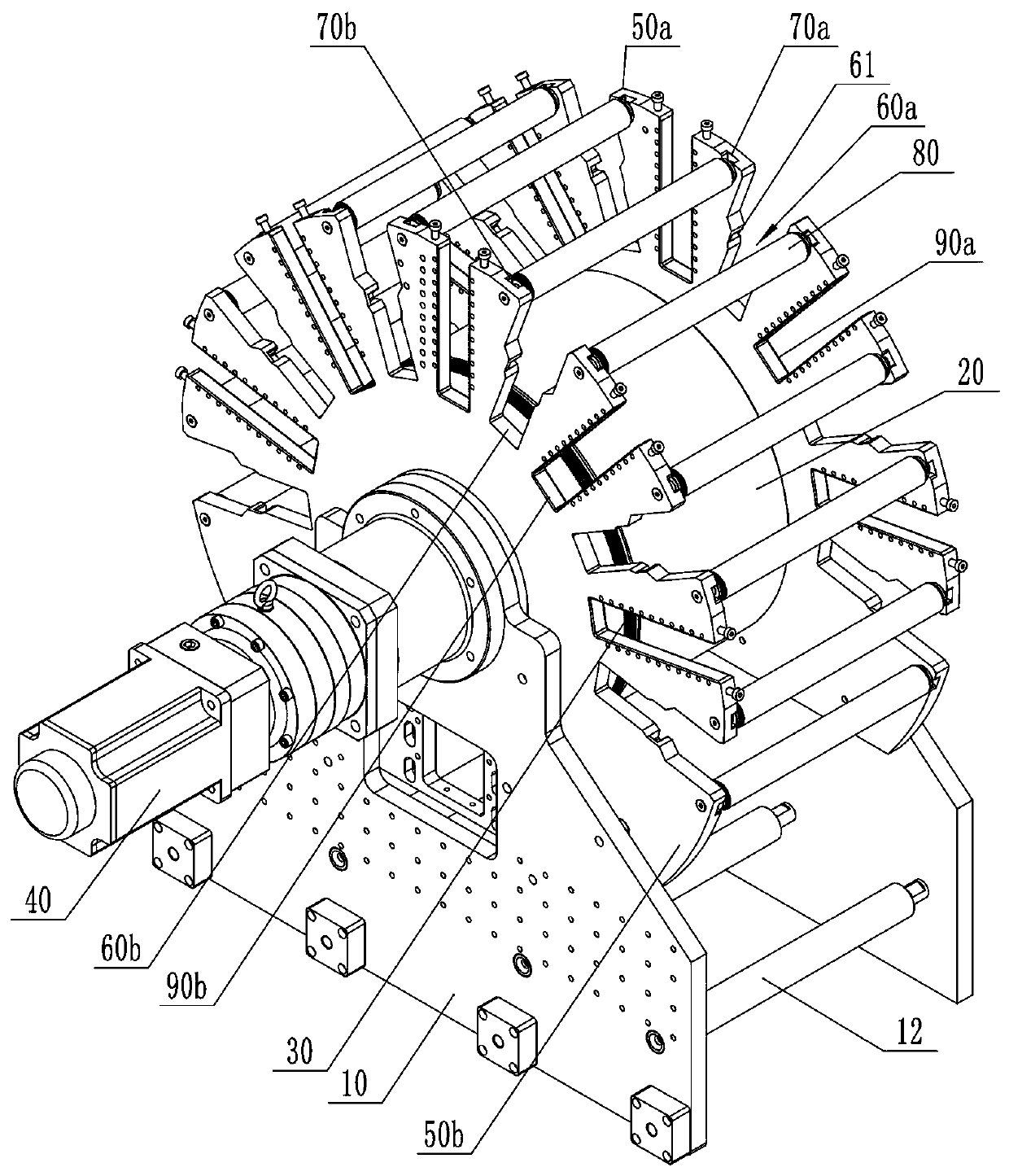
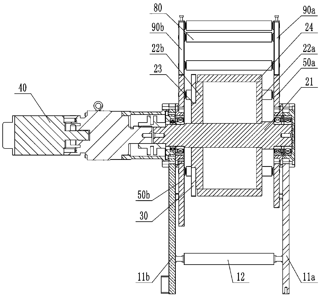
[0020] figure 1 and figure 2 It is a schematic structural diagram of a satellite die-cutting device according to an embodiment of the present invention, wherein, figure 1 A schematic diagram showing a three-dimensional structure of a satellite die-cutting device according to an embodiment of the present invention, figure 2 A schematic cross-sectional structure diagram of the satellite die-cutting device of the present invention is shown. For the convenience of expression, only the parts related to the embodiment of the present invention are shown in the figure.

[0021] Depend on figure 1 and...


PUM


Abstract

The invention belongs to the technical field of die-cutting machines and particularly relates to a satellite type die-cutting device. The satellite type die-cutting device comprises a mounting base, acore shaft rotatably mounted on the mounting base, a driving wheel fixed at the end of the core shaft and arranged coaxially with the core shaft, and a power device, wherein mounting plates fixedly connected with the mounting base are respectively arranged at two ends of the core shaft; a plurality of groups of cutter mounting structures which are arranged around the circumference of the core shaft at intervals are arranged between two mounting plates; guide shaft mounting structures are respectively arranged in positions corresponding to the cutter mounting structures between the two mounting plates; a plurality of die cutters are distributed around the circumference of the core shaft at intervals and are used for simultaneously pressing on the core shaft to carry out die cutting; the plurality of die cutters are used for simultaneously pressing on the core shaft to carry out die cutting; meanwhile, the outer diameter of the core shaft is relatively large; the core shaft can bear higher radial load; after the rotation speed of the core shaft is improved, the rotation speeds of the plurality of die cutters can be greatly improved; the die cutting efficiency can be improved; and meanwhile, the vibration amplitude during operating can be reduced.

Description

technical field [0001] The invention belongs to the technical field of die-cutting machines, in particular to a satellite-type die-cutting device. Background technique [0002] The die-cutting machine is mainly used for die-cutting various shapes of single-sided and double-sided stickers, protective films, gaskets, dust-proof nets, copper and aluminum foils, etc., especially for multi-layer composite products, which can be formed at one time. At present, the cutter mechanism of a die-cutting machine usually includes a base, a cutter and a pressure roller rotatably mounted on the base, and a plurality of cutter mechanisms arranged in sequence along the horizontal direction are arranged on the die-cutting machine. The main problem is that the rotation speed of the existing cutter mechanism is relatively low and the radial load that can be carried is relatively small, which seriously reduces the die-cutting efficiency; and when multiple cutter mechanisms work at the same time, ...

Claims


Application Information

Patent Timeline
IPC IPC(8): B26F1/44B26D7/26
Inventor 宋光辉刘中强庞好光王大龙
Owner SHANDONG HOACO AUTOMATION TECH
Why Eureka
Try Eureka