A conveying device with compression function for biomass fuel

A technology for biomass fuel and conveying equipment, applied in the direction of presses, manufacturing tools, etc., can solve the problems of difficult discharging of materials, poor practicability, and uneconomical discharging methods, so as to improve stability and convenience. Effect

Active Publication Date: 2021-07-02
兴隆县一通新能源科技有限公司
View PDF0 Cites 0 Cited by
  • Summary
  • Abstract
  • Description
  • Claims
  • Application Information

AI Technical Summary

Problems solved by technology

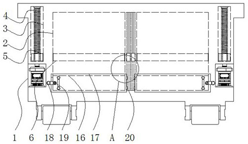
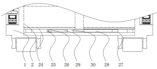
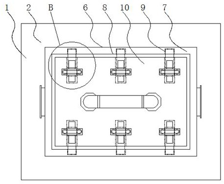
[0004] The purpose of the present invention is to provide a conveying device for biomass fuel with a compression function, so as to solve the problem that the biomass fuel conveying device proposed in the above-mentioned background technology has a loophole in the structural design of the main body, such as the inability to carry out material transportation. The integrated operation of storage and compression leads to poor practicability in the use of equipment. At the same time, it is generally difficult to discharge materials after compression, and general equipment does not have good economical practicability when discharging. way of discharging

Method used


Image

  • A conveying device with compression function for biomass fuel
  • A conveying device with compression function for biomass fuel
  • A conveying device with compression function for biomass fuel

Examples


Embodiment Construction

[0025] The following will clearly and completely describe the technical solutions in the embodiments of the present invention with reference to the accompanying drawings in the embodiments of the present invention. Obviously, the described embodiments are only some, not all, embodiments of the present invention.

[0026] In the description of the present invention, unless otherwise stated, the meaning of "plurality" is two or more; the terms "upper", "lower", "left", "right", "inner", "outer" , "front end", "rear end", "head", "tail", etc. indicate the orientation or positional relationship based on the orientation or positional relationship shown in the drawings, and are only for the convenience of describing the present invention and simplifying the description, rather than Nothing indicating or implying that a referenced device or element must have a particular orientation, be constructed, and operate in a particular orientation should therefore not be construed as limiting ...


PUM


Abstract

The invention relates to a conveying device with a compression function for biomass fuel, comprising a body and a top block. A storage compression chamber is opened inside the body, and side through grooves are opened in the left and right walls of the body. , the inner end of the side penetration groove is connected with a transmission screw, and the outer wall of the transmission screw is connected with a transmission seat, the inner end of the storage compression chamber is installed with a compressor, and the outer side of the compressor is fixed with a locator, A bottom discharge port is arranged at the bottom end of the storage compression chamber, and a sealing plate is installed on the outer side of the bottom discharge port. The beneficial effects of the present invention are: the biomass fuel conveying equipment with compression function is provided with a bottom rod, a top rod and a top block, and through the rotation between the bottom rod and the top rod, the bottom rod can be adjusted through the action of the thread. The distance between the rod and the ejector rod can then achieve the effect of extending the positioner, which is convenient for extending the use or shortening the storage positioner, and improving the convenience and simplicity of its operation.

Description

technical field [0001] The invention relates to the technical field of biomass fuel, in particular to a conveying device with compression function for biomass fuel. Background technique [0002] Biomass fuel: refers to the burning of biomass materials as fuel, generally mainly agricultural and forestry waste (such as straw, sawdust, bagasse, rice bran, etc.), which is mainly different from fossil fuels. In the current national policies and environmental protection standards, directly Burning biomass is a high-pollution fuel, which is only used in large stoves in rural areas and is not allowed to be used in cities. It generally needs to be transported before use. [0003] When the biomass fuel delivery equipment is in use, there are loopholes in the structural design of the main body, such as the inability to carry out the integrated operation of material storage and compression, which leads to poor practicability in the use of the equipment. At the same time, due to the gene...

Claims


Application Information

Patent Timeline
Patent Type & Authority Patents(China)
IPC IPC(8): B30B9/28B30B15/32B30B15/00
Inventor 段亚斌
Owner 兴隆县一通新能源科技有限公司
Why Eureka
Try Eureka