
Automatic tension control device for printing

A tension control and automatic technology, which is applied in transportation and packaging, winding strips, thin material processing, etc., can solve problems such as device failure, abnormal use, and bearing jamming, and achieve the effect of reducing errors and prolonging life

Inactive Publication Date: 2019-06-18
湖南飘派科技有限公司
View PDF0 Cites 0 Cited by
  • Summary
  • Abstract
  • Description
  • Claims
  • Application Information

AI Technical Summary

Problems solved by technology

[0003] However, the existing automatic tension control device still has certain defects in use. Although the existing tension control device can detect the magnitude of the tension and send the signal to the motor to control the speed of the motor, due to the roller installed at one end of the motor and the detection There is a certain distance between the rollers. When the printing paper passes through the detection roller, due to its own gravity, it will bring a certain error to the tension sensor and affect the judgment of the sensor. If the bearing of the detection roller is damaged, the device will malfunction. , when the printing paper is printing, dust or paper powder on the surface will fly into the bearing, which will easily cause the bearing to get stuck and cannot be used normally.

Method used


Image

  • Automatic tension control device for printing
  • Automatic tension control device for printing
  • Automatic tension control device for printing

Examples


Embodiment Construction

[0019] The present invention will be described in further detail below in conjunction with the accompanying drawings and specific embodiments, but the present invention is not limited thereto.

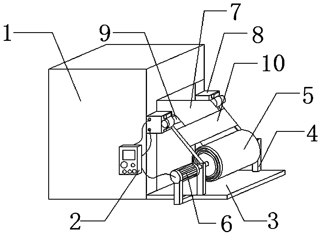
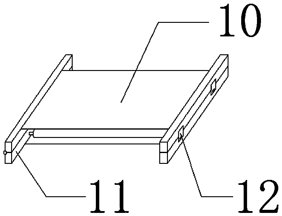
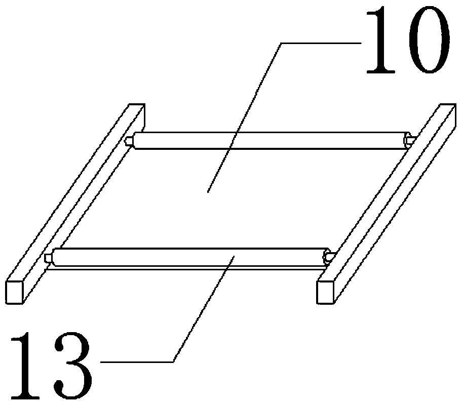
[0020] Such as Figure 1-4 As shown, the present invention includes a printing box 1, a control box 2 is installed on one side of the printing box 1, a bottom plate 3 is arranged at one end of the printing box 1, a support 4 is arranged on the top of the bottom plate 3, a roller 5 is installed at one end of the support 4, and the roller 5 Motor 6 is installed at one end of roller 5, printing paper 7 is sleeved on the outer wall of roller 5, tension sensor 8 is installed in the middle of one end of printing box 1, detection roller 9 is installed on the top of tension sensor 8, and baffle plate is installed between detection roller 9 and roller 5 10. Both sides of the baffle 10 are equipped with support rods 11, one side of one of the support rods 11 is installed with a connecting piece ...


PUM


Abstract

The invention discloses an automatic tension control device for printing. The device comprises a printing box, a control box, a bottom plate, a support, a roller, a motor, printing paper, a tension sensor, a detection roller, a baffle, supporting rods, connecting pieces, rotating rods, a groove and a dust cover. According to the automatic tension control device for printing, the supporting deviceis arranged between the roller and the detection roller, the supporting device is composed of the baffle, the supporting rods and the rotating rods, a rotating bolt is arranged in one supporting rod,the connecting pieces are arranged in the middle of the other supporting rod, the two rotating rods are supported on the top surface of the baffle; during printing, the printing paper is discharged from the roller, penetrates through the two rotating rods, and then enters the printing tank through the detection roller, due to the fact that a certain distance exists between the roller and the detection roller, the rotating rods can fix the printing paper, the error caused by the tension of the detection roller due to the gravity of the paper can be prevented, the error of tension control can bereduced, and the service life of the detection roller can be prolonged.

Description

technical field [0001] The invention relates to an automatic tension control device for printing. Background technique [0002] Automatic tension controller is mainly composed of tension detector, high-precision A / D, D / A converter, high-performance single-chip microcomputer and so on. The automatic constant tension controller is based on the comparison between the tension of the coil measured by the tension detector and the set target tension, and automatically adjusts the D / A output through the PID operation of the single-chip microcomputer to change the magnetic powder clutch, the excitation current of the brake or the servo motor. It can be widely used in various occasions that require precise measurement and control of tension, and has flexible use and wide applicability. [0003] However, the existing automatic tension control device still has certain defects in use. Although the existing tension control device can detect the magnitude of the tension and send the signa...

Claims


Application Information

Patent Timeline
Patent Type & Authority Applications(China)
IPC IPC(8): B65H26/04B65H23/185
Inventor 曾利明
Owner 湖南飘派科技有限公司
Learn More