A high-pressure ultra-high pressure shielded electric control valve

An electric regulating valve and ultra-high pressure technology, applied in electric components, lift valves, valve devices, etc., can solve the problems of unreliable sealing, inconvenient installation and maintenance, and inability to eliminate expansion and contraction.

Active Publication Date: 2020-03-24
山东双超生物设备科技有限公司 +1
View PDF9 Cites 0 Cited by
  • Summary
  • Abstract
  • Description
  • Claims
  • Application Information

AI Technical Summary

Problems solved by technology

Authorized by the State Intellectual Property Office of China on December 31, 2008, the authorized announcement number is CN100447460C, and the invention patent named "motor-operated valve" has a protective cover between the stator and rotor of the motor to seal the regulated medium In the protective cover, the dynamic seal is cancelled, and no leakage can be achieved. However, as the pressure increases, the thickness of the protective cover will increase to meet the strength requirements, which will rapidly reduce the efficiency of the motor.
Authorized by the State Intellectual Property Office of China on November 30, 2011, the authorized announcement number is CN101858455 B, and the invention patent named "an electric control valve" uses a motor housing to seal the motor, motor gear, transmission gear, and screw gear. It saves the dynamic seal, but the patented technology places the motor directly in the environment of the regulating medium, so it cannot be applied to the corrosive regulating medium
Authorized by the State Intellectual Property Office of China on June 16, 2010, the authorized announcement number is CN101359849B, and the invention patent named "High-voltage and ultra-high-voltage medium environment shielded motor" makes the shielding sleeve not able to bear the pressure, but only to isolate the medium The role of the combination provides favorable conditions for the combination of innovative high-pressure and ultra-high-pressure shielded electric control valves; however, the shielding sleeve and pressure balance diaphragm in this patent are sealed with O-rings, and the seal is not reliable enough; the shielding sleeve and pressure balance diaphragm cannot be structurally Eliminate the volume expansion and contraction of the inert liquid due to the difference between the filling temperature and the working temperature of the inert liquid, which may easily damage the shielding sleeve and the pressure balance diaphragm due to thermal stress; it is difficult to connect the lead wires of the motor stator, and it is not easy to install and maintain. Implementation of this technology in combination with innovative high-pressure and ultra-high pressure shielded electric control valves

Method used


Image

  • A high-pressure ultra-high pressure shielded electric control valve
  • A high-pressure ultra-high pressure shielded electric control valve
  • A high-pressure ultra-high pressure shielded electric control valve

Examples


Embodiment Construction

[0050] The embodiments of the present invention will be described in detail in conjunction with the accompanying drawings.

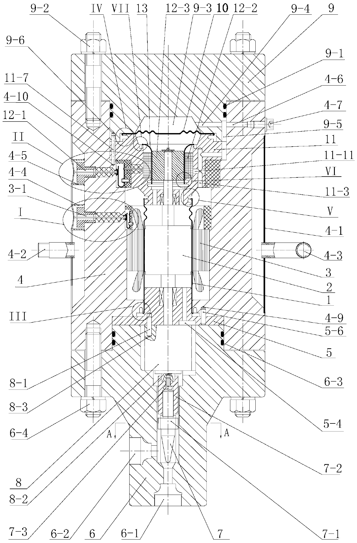
[0051] Such as figure 1 As shown, the technical solution of the present invention is composed of valve body 6, reducer 8, valve core assembly 7, motor housing 4, motor stator 3, motor lead wire assembly 3-1, shielding sleeve 1, motor rotor 2, valve body End bearing assembly 5, rear cover 9, rear cover end resolver and bearing assembly 11, resolver 12, resolver lead wire assembly 12-1, secondary shielding sleeve 13 and pressure balance diaphragm 10 constitute.

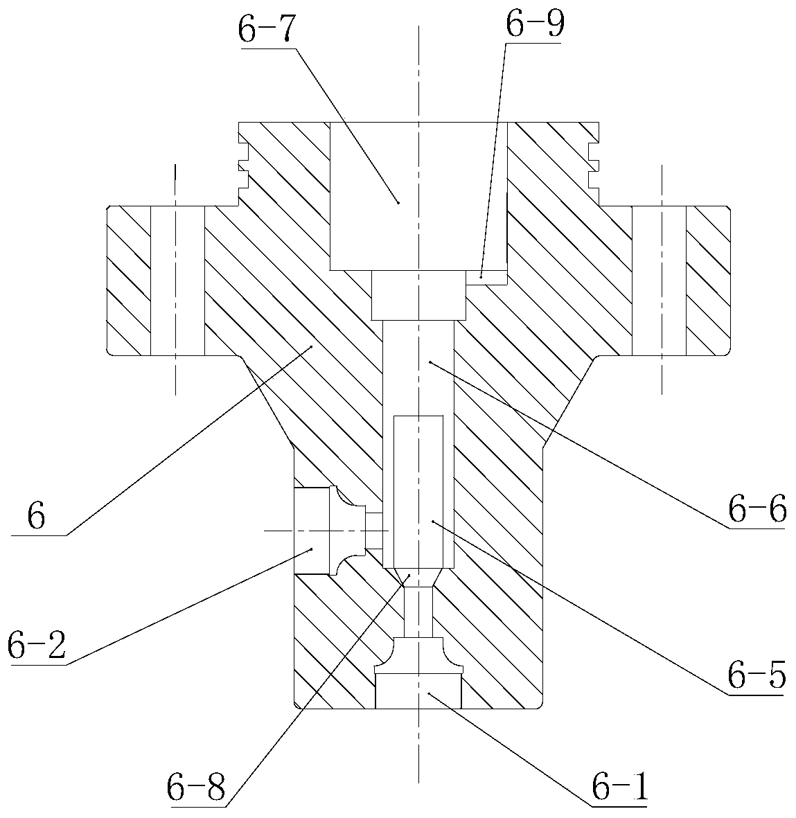
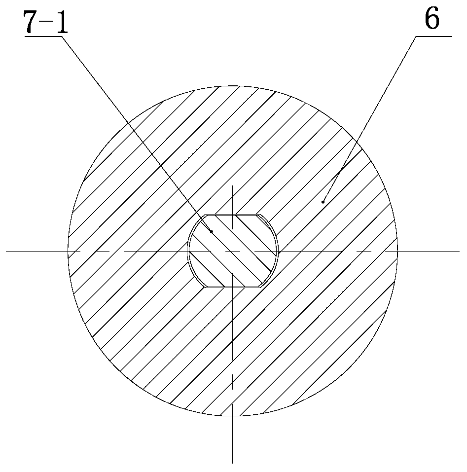
[0052] Such as figure 2 , image 3 As shown, the valve body 6 is a combination composed of a flat cover with a boss, a cylinder, and a coaxial transitional cone between the two. S30408 ​​stainless steel forgings are selected; Hole 6-7, drive sleeve movement hole 6-6, valve core movement chamber 6-5, valve port 6-8 and valve inlet 6-1; from the outer cylindrical surface of the cylinder to the v...


PUM


Abstract

The invention relates to the field of shielding electric adjusting valves, in particular to a high-pressure and ultra-high-pressure shielding electric adjusting valve. The valve is composed of a valvebody, a reducer, a valve core assembly, a motor housing, a motor stator, a motor leading wire assembly, a shielding sleeve, a motor rotor, a valve body side bearing assembly, a rear cover, a rear cover side rotary converter, a bearing assembly, a rotary converted, a secondary shielding sleeve, a rotary converted leading wire assembly and a pressure balancing diaphragm. The electric adjusting valve has the advantages that the defect of motor efficiency reduction due to the increasing of the pressure of an adjusting medium and the thickening of the motor shielding sleeve which is also called protective sleeve of an existing shielding electric adjusting valve is overcome and the defects of the damage of the pressure balancing diaphragm and the shielding sleeve, the difficulty of motor statorleading wire installing connection and the like caused by unstable sealing of an existing matching component 'high-pressure and ultra-high pressure medium environment shielding motor' and the expansion and retraction through heat and cold respectively of inert liquid contained in the stator are overcome, the sealing of the high-pressure and ultra-high-pressure shielding electric adjusting valve is allowed to be reliable, the shielding sleeve is not influenced by the expansion and retraction caused by heat and cold respectively of the inert liquid, and the installing and maintaining are convenient.

Description

[0001] 1. Technical field [0002] The invention relates to the field of electric control valves, in particular to a high-pressure and ultra-high pressure shielded electric control valve. [0003] 2. Technical background [0004] Electric regulating valve is an important execution unit in industrial automation process control. Compared with traditional pneumatic or hydraulic regulating valves, it only consumes energy during work, and does not need complicated pneumatic or hydraulic pipelines and corresponding workstations. It is quick to install The advantages of convenience and fast action speed. The structure of the electric regulating valve is similar, and it is mainly composed of a controller, an actuator, which is generally a motor, a valve stem, and a valve core assembly. Authorized by the State Intellectual Property Office of China on December 31, 2008, the authorized announcement number is CN100447460C, and the invention patent named "motor-operated valve" has a protec...

Claims


Application Information

Patent Timeline
Patent Type & Authority Patents(China)
IPC IPC(8): F16K1/32F16K1/38F16K27/02F16K27/08F16K31/04F16K31/53H02K3/50H02K5/06H02K5/22H02K7/116H02K11/21
Inventor 王威强王胜德曲延鹏瞿德浩
Owner 山东双超生物设备科技有限公司
Why Eureka
Try Eureka