
Fluid control valve and fluid control valve assembling method

A technology of fluid control valves, assembly methods, applied to parts in contact between valve elements and valve seats, valve operating/releasing devices, valve devices, etc., capable of solving the problems of no representation, no insight into the correlation, etc., Achieve good adaptability, good durability, and suppress the change of Cv value

Active Publication Date: 2019-06-18
KAISHI SCT CO LTD
View PDF8 Cites 1 Cited by
  • Summary
  • Abstract
  • Description
  • Claims
  • Application Information

AI Technical Summary

Problems solved by technology

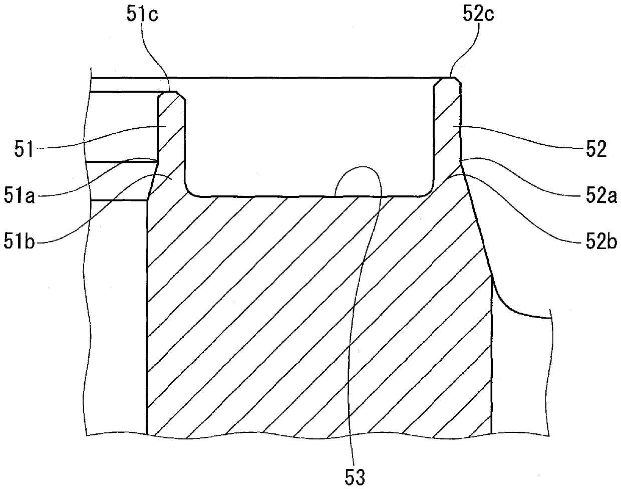
[0015] On the other hand, in Patent Document 2, only the diaphragm side is considered, and as described above, the problem of further reducing the deterioration of the Cv value after many times of opening and closing in a high-temperature environment is solved by using a valve stroke adjustment mechanism. The proposal, regarding the valve seat that the inventors of the present application also focused on, mentions thermal expansion and aging, but there is no specific information on the valve seat and the diaphragm pressing part related to such problems or their mutual relationship. express
That is, the upper surface (engagement surface) of the valve seat in this document is only a narrow ring-shaped horizontal surface or a circular protrusion, and it is still unclear about the valve seat and the diaphragm pressing part and their relationship. get any insight

Method used


Image

  • Fluid control valve and fluid control valve assembling method
  • Fluid control valve and fluid control valve assembling method
  • Fluid control valve and fluid control valve assembling method

Examples


Embodiment Construction

[0050] Hereinafter, an embodiment (this example) of the fluid control valve of the present invention will be described in detail with reference to the drawings. The fluid control valve in this example is a diaphragm valve using a diaphragm, such as figure 1 , figure 2 As shown, it is a valve with an annular valve seat 2 and a diaphragm 1, the annular valve seat 2 is arranged in a valve body 14, 32 having an inlet 4 and an outlet 5, and the diaphragm 1 is opposite to the ring shaped valve seat 2 and abuts / leaves (takes off) under the lifting motion of the rod 12, 40, figure 1 A longitudinal sectional view showing an example of the valve of the present invention, figure 2 It is a longitudinal sectional view showing another example of the valve of the present invention.

[0051] In addition, as will be described later, these valve structures are respectively equipped with actuator bodies 11 and 33, and the rods 12 and 40 in this figure are rods for actuators, but the valve o...


PUM


Abstract

The object of the invention is to provide a fluid control valve for use under high-temperature conditions and capable of achieving high durability and Cv value stability even with many operations, anda method of assembling the fluid control valve. The fluid control valve includes an annular valve seat provided inside a body having an inflow port and an outflow port and a diaphragm opposed to theannular valve seat to be in contact therewith or away therefrom by an ascending / descending motion of an actuator rod or a manual rod. A contact surface, which is an upper surface of the annular valveseat, has a tapered surface formed along a centripetal direction of the annular valve seat.

Description

technical field [0001] The present invention relates to a fluid control valve and an assembling method of the fluid control valve capable of exhibiting the stability of Cv value variation with high precision even through a very large number of opening and closing operations in a high-temperature environment. Background technique [0002] Conventionally, as a fluid control valve used in a high-temperature environment, a so-called direct contact metal diaphragm valve is known. The thin film (metal diaphragm) is the valve diaphragm; in the state where the outer peripheral side is clamped between the valve body and the bonnet, the outer sealing part is formed in a ring shape around the valve chamber; the central part is passed by an actuator that is moved up and down, etc. The rod is pushed, and the upper surface of the annular valve seat provided on the periphery of the opening of the primary side flow path in the valve chamber is abutted and tightly contacted to close the valv...

Claims


Application Information

Patent Timeline
Patent Type & Authority Applications(China)
IPC IPC(8): F16K7/12F16K7/17
CPCF16K31/1221F16K31/1225F16K7/17F16K25/00F16K7/12F16K27/0236F16K31/122
Inventor 堀口肇
Owner KAISHI SCT CO LTD
Learn More