Environment-friendly waste incinerator

An incineration device and waste technology, applied in incinerators, combustion methods, combustion types, etc., can solve the problems of increasing incineration time, single structure, polluting the environment, etc., and achieve the effect of increasing permeability and avoiding damage.

Inactive Publication Date: 2019-06-18
刘妍
View PDF0 Cites 2 Cited by
  • Summary
  • Abstract
  • Description
  • Claims
  • Application Information

AI Technical Summary

Problems solved by technology

[0003] Most of the existing waste incineration devices are containers with a single structure, and the waste is directly placed in the open air to be ignited or burned in a sealed interior, because waste and waste are generally piled up to a certain extent before they are incinerated, which takes a long time The accumulation of waste will cause agglomeration of waste, and directly discharging the agglomerated waste into the combustion vessel will lead to incomplete combustion, or it will take a long time to incinerate and increase the incineration time. A large amount of smoke or harmful gas will be produced. If the one-time incineration is not complete, more smoke will be generated during the burning time, which will seriously pollute the environment; in addition, a large amount of heat will be generated when incinerating waste, and the heat will accumulate to a certain extent. More or less, it will cause certain damage to the equipment, reduce the service life of the device, and increase the cost. At the same time, the smoke generated by incineration cannot be effectively treated, which will pollute the environment.

Method used


Image

  • Environment-friendly waste incinerator
  • Environment-friendly waste incinerator
  • Environment-friendly waste incinerator

Examples


Embodiment Construction

[0029] For the convenience of those skilled in the art to understand, the following in conjunction with the attached Figure 1-8 , to further specifically describe the technical solution of the present invention.

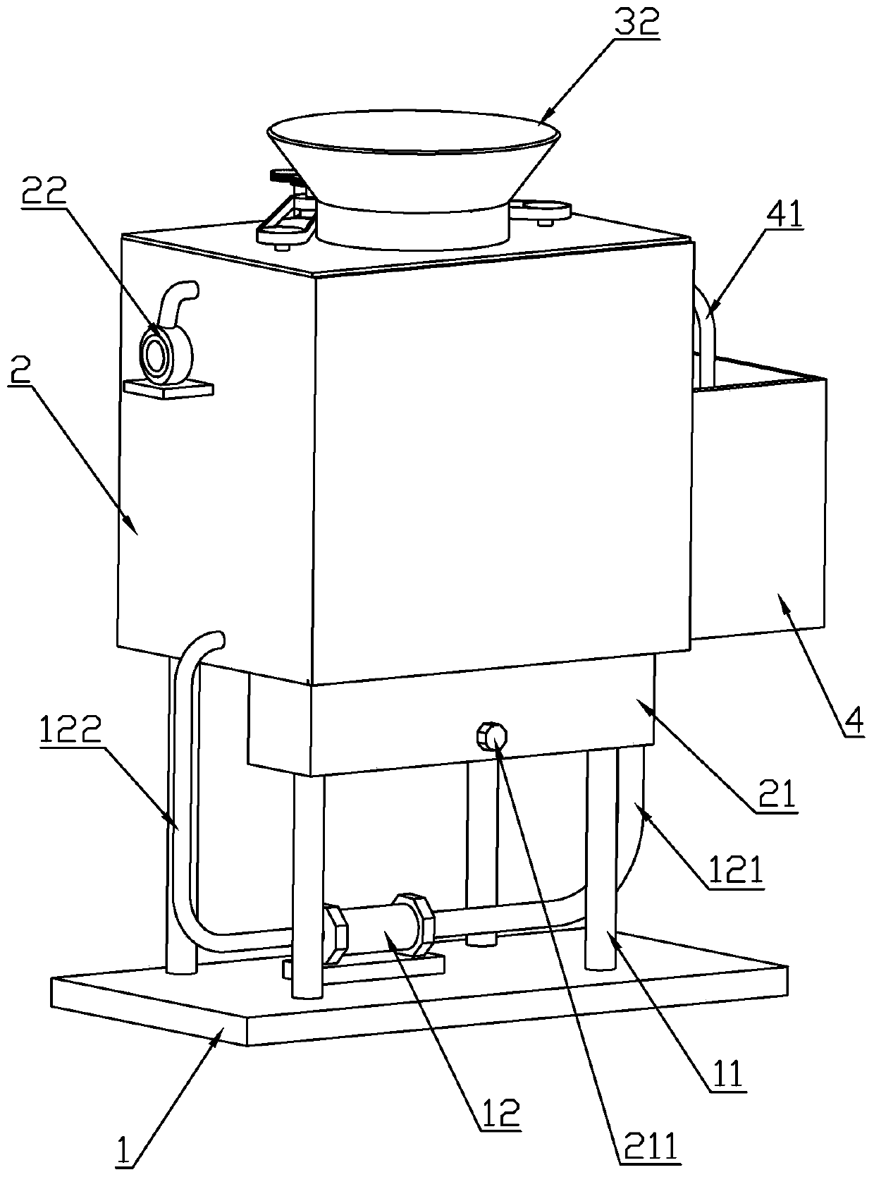
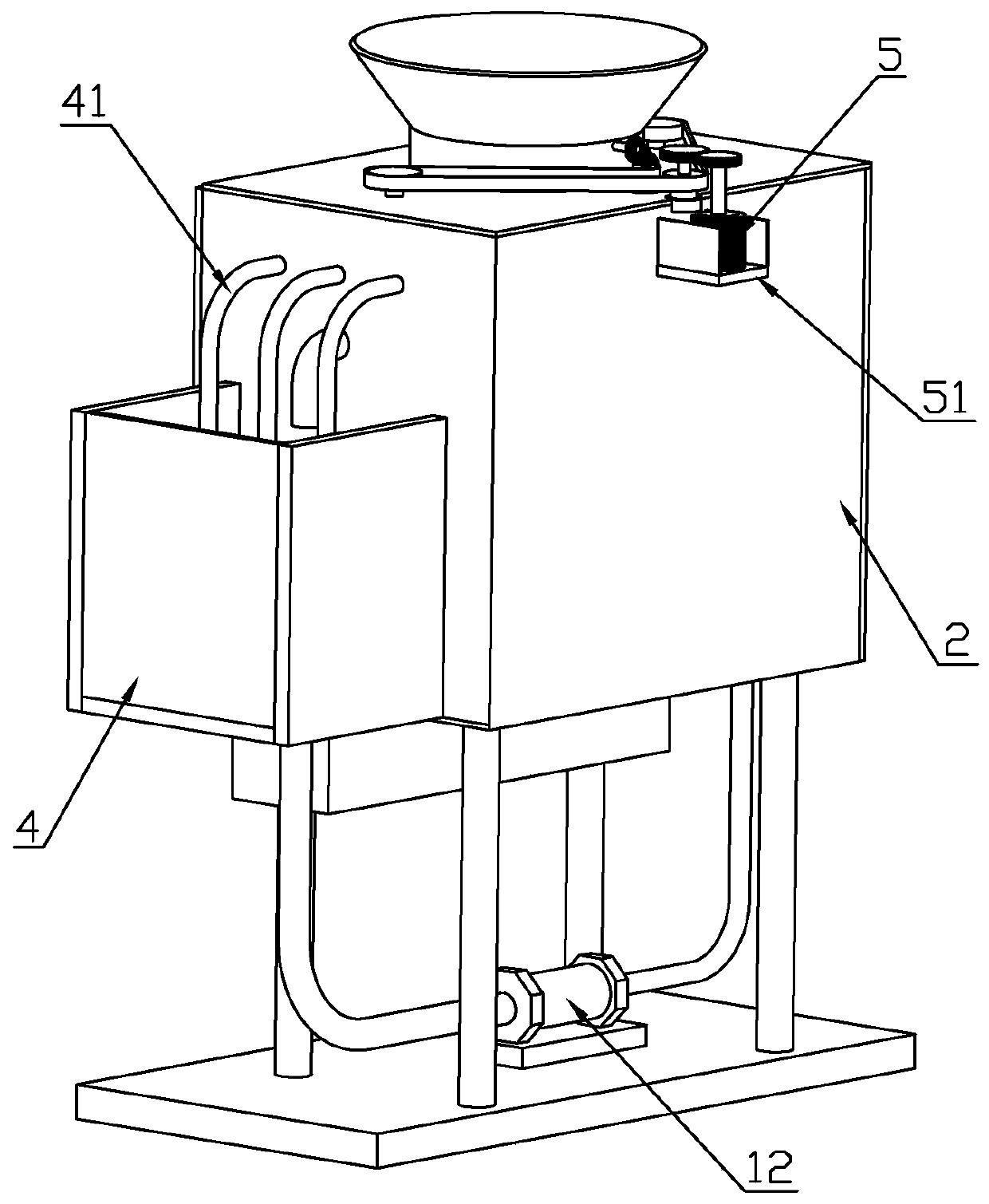
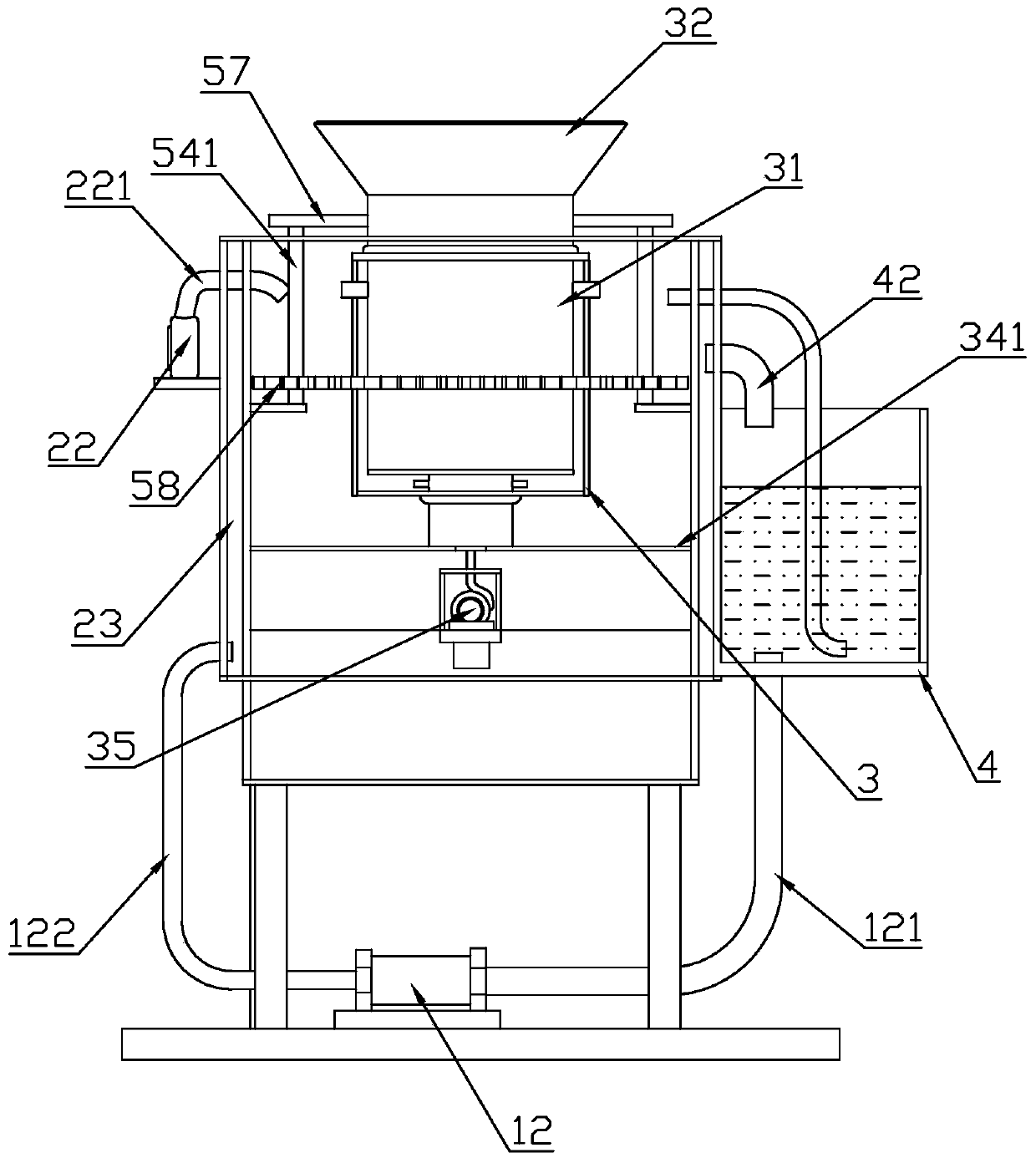
[0030]An environmentally friendly waste incineration device, including a base plate 1, a heat insulation box 2, an incineration outer cylinder 3, a cold water tank 4, and a transmission motor 5. The base plate 1 is placed on the ground to stably support the device. The base The top side of the plate 1 is provided with a number of support columns 11, and the top of the support columns 11 is connected with a heat insulation box 2, and the heat insulation box 2 is a double-layer structure with a heat insulation interlayer 23 inside. A cold water tank 4 is fixedly connected, and the cold water tank 4 is used to hold cooling water. The bottom side of the cold water tank 4 is provided with a water delivery pipe 121. One end of the water delivery pipe 121 extends sealingly...


PUM


Abstract

The invention discloses an environment-friendly waste incinerator. The environment-friendly waste incinerator comprises a base plate, a heat insulated box, an incineration outer barrel, a cooling water tank and a driving motor. The base plate is flatly placed on the ground and used for stably supporting the device. The top side of the base plate is provided with a plurality of supporting columns.The top ends of the supporting columns are connected with the heat insulated box. The heat insulated box is of a double-layer structure and is internally provided with a heat insulation interlayer. One side of the heat insulated box is fixedly connected with the cooling water tank. The cooling water tank is used for containing cooling water. The top end of the incineration outer barrel is connected with a transition barrel. The incineration outer barrel is rotatably connected with the transition barrel. The transition barrel penetrates through the heat insulated box in a sealed mode. The top end of the transition barrel is fixedly connected with a feed port. An air blower I is arranged on one side of the heat insulated box. The air blower I is connected with an air pipe I. The air pipe I extends into the heat insulated box in a sealed mode. The environment-friendly waste incinerator is reasonable in structure, facilitates thorough incineration on waste and can filter waste gas.

Description

technical field [0001] The invention belongs to the technical field of waste treatment devices, in particular to an environment-friendly waste incineration device. Background technique [0002] With the rapid development of the economy, people's living standards continue to improve, and people's demand for life is increasing, which also produces more and more garbage or waste. When more and more waste affects people's life Finally, these wastes need to be treated. Generally, people will incinerate or landfill these wastes, but landfills will leave many problems such as soil pollution, so incineration is more common. [0003] Most of the existing waste incineration devices are containers with a single structure, and the waste is directly placed in the open air to be ignited or burned in a sealed interior, because waste and waste are generally piled up to a certain extent before they are incinerated, which takes a long time The accumulation of waste will cause agglomeration o...

Claims


Application Information

Patent Timeline
Patent Type & Authority Applications(China)
IPC IPC(8): F23G5/20F23G5/44F23J15/04
Inventor 刘妍
Owner 刘妍
Why Eureka
Try Eureka