Combustion chamber

A combustion chamber and fuel oil technology, applied in the field of combustion chamber, can solve the problems of high cost, high combustion temperature, and easy damage to the deflector.

Active Publication Date: 2019-06-18
AECC HUNAN AVIATION POWERPLANT RES INST
View PDF6 Cites 2 Cited by
  • Summary
  • Abstract
  • Description
  • Claims
  • Application Information

AI Technical Summary

Problems solved by technology

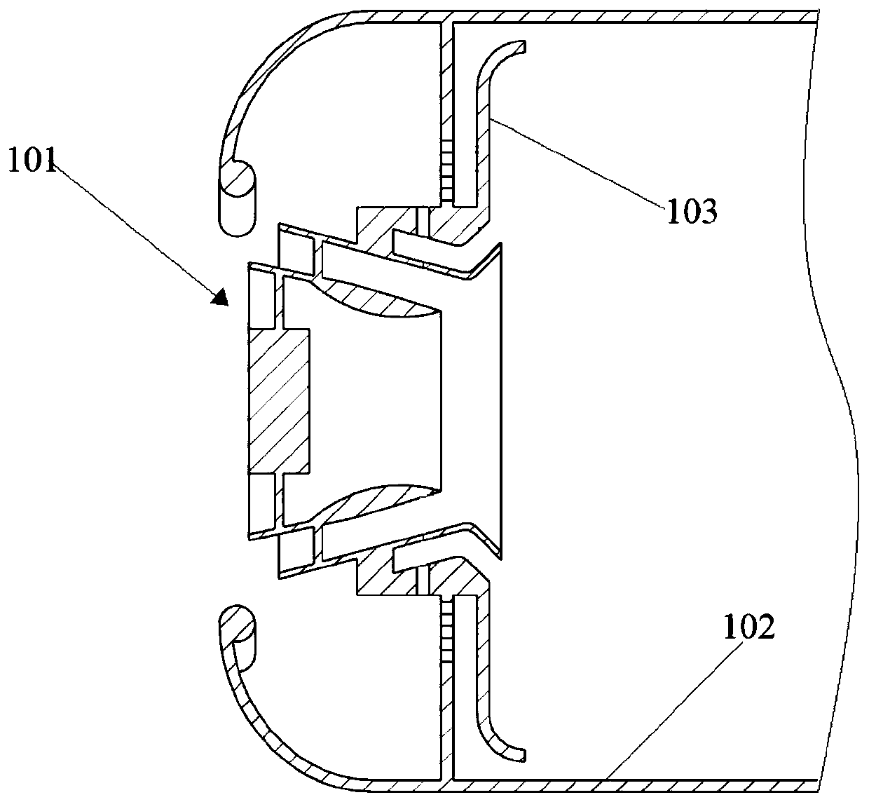
At present, the cooling of the wall surface is mainly achieved by setting up deflectors to control the flow of cooling airflow. However, the deflectors are generally located in the main combustion area, and the combustion temperature is high, which is easy to damage the deflectors. The cooling effect is poor and the cost is relatively high. high

Method used


Image

  • Combustion chamber
  • Combustion chamber
  • Combustion chamber

Examples


Embodiment Construction

[0031] Example embodiments will now be described more fully with reference to the accompanying drawings. Example embodiments may, however, be embodied in many forms and should not be construed as limited to the embodiments set forth herein; rather, these embodiments are provided so that this disclosure will be thorough and complete, and will fully convey the concept of example embodiments to those skilled in the art. The same reference numerals in the drawings denote the same or similar structures, and thus their detailed descriptions will be omitted.

[0032] Although relative terms such as "upper" and "lower" are used in this specification to describe the relative relationship of one component of an icon to another component, these terms are used in this specification only for convenience, for example, according to the description in the accompanying drawings directions for the example described above. It will be appreciated that if the illustrated device is turned over so...


PUM

PropertyMeasurementUnit
Apertureaaaaaaaaaa

Abstract

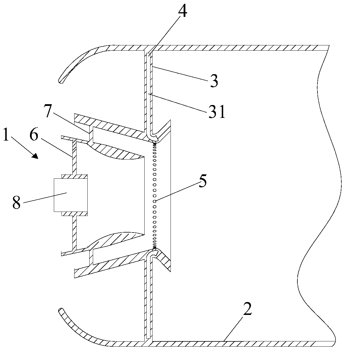
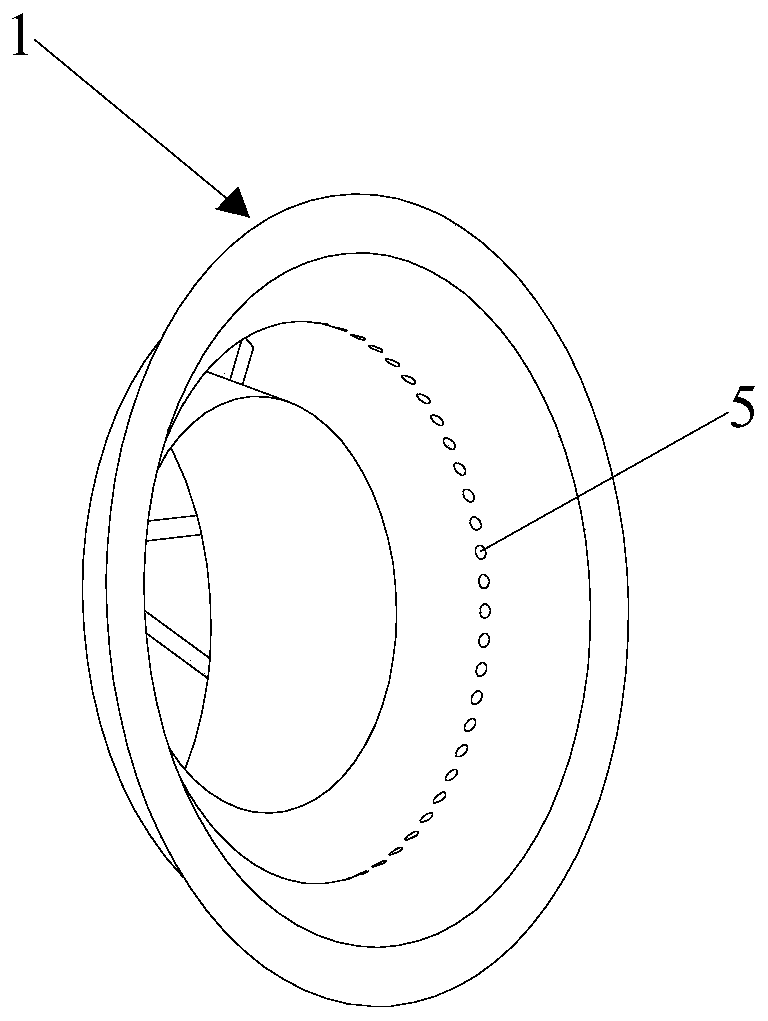
The invention provides a combustion chamber, and relates to the field of aero-engines. The combustion chamber comprises a combustion chamber head and a flame tube. In addition, the combustion chambercomprises a splash plate and a first-stage oil supply system, wherein the splash plate is arranged between the combustion chamber head and the flame tube, and connected to the periphery of the combustion chamber head; a cavity is formed in the splash plate, and an oil outlet hole communicating with the cavity and the combustion chamber head is formed in the side wall of the combustion chamber head; and the first-stage oil supply system is arranged at the end, away from the combustion chamber head, of the splash plate, communicates with the cavity , and is used for injecting fuel oil into the cavity. According to the combustion chamber, the wall face cooling effect can be enhanced, and the production cost can be reduced.

Description

technical field [0001] The present disclosure relates to the field of aero-engines, and in particular, to a combustion chamber. Background technique [0002] With the development of aerospace technology, the requirements for aero-engines are getting higher and higher. The combustion chamber is the core component of the engine and is used to convert the chemical energy in the fuel into heat energy. The combustion chamber is in a high-temperature and high-stress environment for a long time, and it is prone to failures such as deflector ablation and head wall ablation, which directly cause the engine to fail to work normally. In order to make the engine work normally under different working conditions, it is necessary to design the combustion chamber more carefully. [0003] Because the high-temperature gas generated during the combustion of fuel will damage and ablate the wall of the combustion chamber head, it is very important to cool the wall of the combustion chamber hea...

Claims


Application Information

Patent Timeline
IPC IPC(8): F23R3/28
Inventor 汪玉明王梅娟江立军彭中九蒋尧冯阳陈盛刘丽娟张荣幸
Owner AECC HUNAN AVIATION POWERPLANT RES INST
Why Eureka
Try Eureka