A Speed ​​Planning Method for Acceleration and Deceleration of CNC Machine Tool under Constant Force Constraint

A technology of speed planning and constraint conditions, applied in the direction of digital control, electrical program control, etc., can solve the problems that the performance of the servo motor system cannot be maximized, the servo motor system cannot be effectively guaranteed, and the speed planning method is not safe, etc., to achieve increased stability performance, improve processing efficiency, and reduce the effect of following error

Active Publication Date: 2020-07-28
TSINGHUA UNIV
View PDF10 Cites 0 Cited by
  • Summary
  • Abstract
  • Description
  • Claims
  • Application Information

AI Technical Summary

Problems solved by technology

Therefore, using a planning method based on kinematic parameters as constraints does not maximize the performance of the servo motor system
[0008] In addition, the use of kinematic parameters such as maximum speed and maximum acceleration parameters to constrain the speed planning process of the CNC system cannot effectively ensure that the maximum torque (for rotary motors) or maximum torque (for linear motors) of the servo motor system that controls the motion of the machine tool satisfies requirements, there may be torque (for rotary motors) or torque (for linear motors) overloading of the servo system
Therefore, the velocity planning method based on kinematic constraints is not safe

Method used


Image

  • A Speed ​​Planning Method for Acceleration and Deceleration of CNC Machine Tool under Constant Force Constraint
  • A Speed ​​Planning Method for Acceleration and Deceleration of CNC Machine Tool under Constant Force Constraint
  • A Speed ​​Planning Method for Acceleration and Deceleration of CNC Machine Tool under Constant Force Constraint

Examples


Embodiment Construction

[0036] Below in conjunction with accompanying drawing and embodiment technical scheme of the present invention is described in detail as follows:

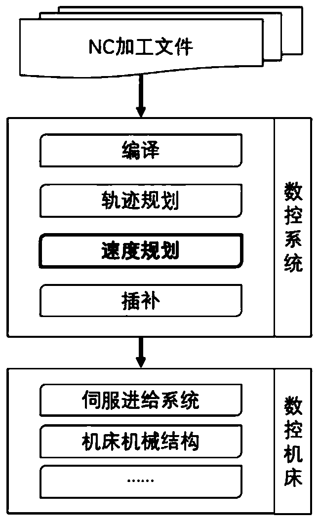
[0037] The acceleration and deceleration speed planning method of a CNC machine tool under the constant force constraint condition proposed by the present invention is different from the traditional numerical control system speed planning method based on kinematic parameters such as maximum speed, maximum acceleration and maximum jerk. The present invention uses power The scientific parameters - the maximum torque of the servo motor system (for rotary motors) or the maximum torque (for linear motors) are used as constraints for the speed planning of the CNC system. The concrete realization process of the inventive method is as follows:

[0038] 1) Obtain calculation parameters, including:

[0039] 1.1) Obtain the dynamic parameters of the servo feed system in the CNC system, including the maximum torque value (for rotary motors) o...


PUM


Abstract

The invention provides a numerical control (NC) machine tool acceleration and deceleration speed planning method under constant force constraints and belongs to the acceleration and deceleration speedprocessing technology field of NC processing. The method comprises steps that firstly, calculation parameters are obtained, including kinetic parameters of a servo feed system in a NC system, machining start point and end point coordinates of a current command segment of a to-be-planned NC machining file, the machining start point speed, the machining end point speed and the feed command speed; the function relationship between the servo command speed and the acceleration under the constant force constraints is determined; a formula for calculating the total exercise time of various speed planning segments is obtained; function relationships between the servo command acceleration and the processing time, between the servo command speed and the processing time, and between the servo command position and the processing time under the constant force constraints are determined in turn; according to the above parameters and the function relationships, speed planning of various speed planning segment is completed. The method is advantaged in that the kinetic parameters are used as the constraints for speed planning of the NC system, machining accuracy of the workpiece can be improved, and stability and processing efficiency of the NC system are improved.

Description

technical field [0001] The invention belongs to the technical field of acceleration and deceleration processing of numerical control machining, and in particular relates to a planning method for acceleration and deceleration speed of a numerical control machine tool under constant force constraints. Background technique [0002] The CNC system is the core control device of the CNC machine tool, see figure 1 , which is the work flow chart of the existing CNC system. The CNC system completes the processing of the workpiece according to the input NC (Numerical Control) processing file. The NC processing file is a file describing the tool path trajectory, and the tool path trajectory is usually described in the G code (ISO6983) format. The CNC system needs to use the speed planning method for speed planning according to the tool path trajectory, and then complete the interpolation of the tool trajectory by the interpolation method, and finally send the interpolation data to the...

Claims


Application Information

Patent Timeline
Patent Type & Authority Patents(China)
IPC IPC(8): G05B19/416
Inventor 李炳燃叶佩青张辉
Owner TSINGHUA UNIV
Why Eureka
Try Eureka