Pixel driving circuit, display device and pixel driving method

A technology of pixel driving circuit and driving module, applied in static indicators, instruments, etc., can solve the problems of uneven display brightness and uneven driving current of OLED devices, achieve stable and uniform display brightness, improve quality, and reduce distortion. Effect

Active Publication Date: 2020-11-17
BOE TECH GRP CO LTD +1
View PDF10 Cites 0 Cited by
  • Summary
  • Abstract
  • Description
  • Claims
  • Application Information

AI Technical Summary

Problems solved by technology

[0005] In view of the shortcomings of the existing methods, the present application proposes a pixel driving circuit, a display device and a pixel driving method to solve the problem of the display of each OLED device caused by the uneven driving current caused by the difference in the threshold voltage of each driving transistor in the prior art. Technical problem of uneven brightness

Method used


Image

  • Pixel driving circuit, display device and pixel driving method
  • Pixel driving circuit, display device and pixel driving method
  • Pixel driving circuit, display device and pixel driving method

Examples


Embodiment Construction

[0045] The present application is described in detail below, and examples of embodiments of the present application are shown in the drawings, wherein the same or similar reference numerals represent the same or similar components or components having the same or similar functions throughout. Also, detailed descriptions of known technologies will be omitted if they are not necessary to illustrate the features of the present application. The embodiments described below by referring to the figures are exemplary only for explaining the present application, and are not construed as limiting the present application.

[0046] Those skilled in the art can understand that, unless otherwise defined, all terms (including technical terms and scientific terms) used herein have the same meanings as commonly understood by those of ordinary skill in the art to which this application belongs. It should also be understood that terms, such as those defined in commonly used dictionaries, should ...


PUM


Abstract

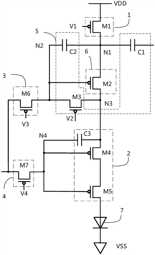
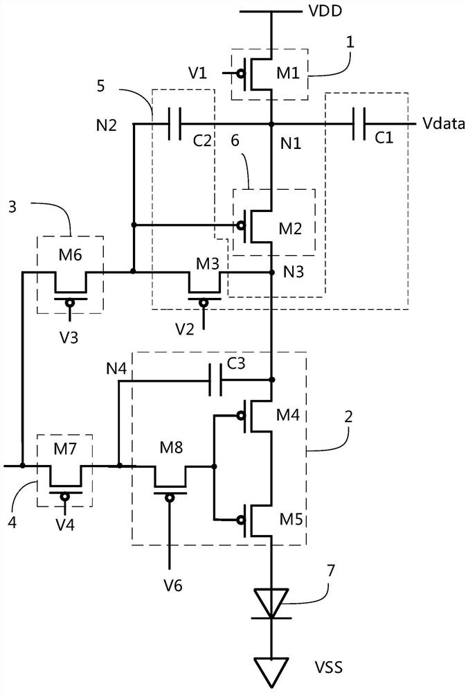
Embodiments of the present application provide a pixel driving circuit, a display device, and a pixel driving method. In the pixel driving circuit, the first to fifth terminals of the threshold voltage compensation module are respectively electrically connected to the first node, the second node, the data signal source, the third node, and the second signal source; the first to the third terminals of the driving module Terminals are respectively electrically connected to the first node, the third node and the second node; the first to third terminals of the first switch module are respectively electrically connected to the power supply, the first node and the first signal source; the first terminal of the second switch module The first to third ends of the third switch module are respectively electrically connected to the fifth signal source, the second node, and the third signal source; the fourth The first to third ends of the switch module are respectively electrically connected to the fifth signal source, the fourth node, and the fourth signal source. The embodiment of the present application can effectively compensate the threshold voltage of the driving transistor.

Description

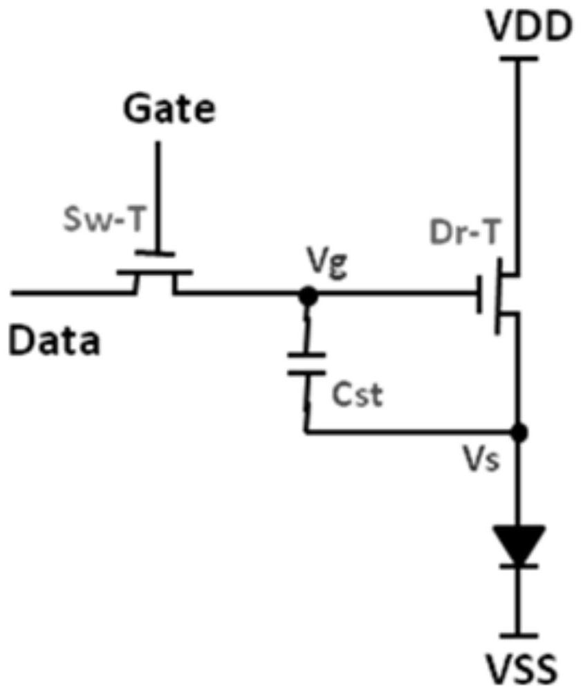
technical field [0001] The present application relates to the field of display technology, in particular, the present application relates to a pixel driving circuit, a display device and a pixel driving method. Background technique [0002] Organic Light-Emitting Diode (OLED, Organic Light-Emitting Diode), as a current-mode light-emitting device, has been increasingly used in new generation display devices. [0003] The basic OLED driving circuit is 2T1C. The OLED driving circuit of 2T1C includes two thin film transistors (TFT, Thin Film Transistor) and a capacitor (C, Capacitance). The value of the driving current (that is, the current flowing through the driving transistor) can determine the brightness generated by the OLED device, and the magnitude of the driving current is related to the threshold voltage of the driving transistor. [0004] Due to the manufacturing process factors of the transistors, the characteristics of the transistors in different regions of the di...

Claims


Application Information

Patent Timeline
Patent Type & Authority Patents(China)
IPC IPC(8): G09G3/3208
CPCG09G2300/0819G09G2300/0852G09G2310/0262G09G2300/043G09G2320/045G09G3/3233G09G2320/0233G09G2330/02
Inventor 何静汤春苗李挺曹中林徐元杰臧鹏程李瑶
Owner BOE TECH GRP CO LTD
Why Eureka
Try Eureka