
Jack-free socket based on electromagnetic induction and conversion plug matched with same

A technology of electromagnetic induction and conversion plug, which is applied in the direction of circuits, electrical components, coupling devices, etc., can solve the problems of ineffective contact between the transmitting module and the receiving device, the failure of the function of the electric socket, and the reduction of the receiving power, so as to avoid electrical wires. Effects of tripping, increasing electric power, and reducing electromagnetic interference

Pending Publication Date: 2019-06-18
浙江理工大学上虞工业技术研究院有限公司 +1
View PDF3 Cites 2 Cited by
  • Summary
  • Abstract
  • Description
  • Claims
  • Application Information

AI Technical Summary

Problems solved by technology

This patent is based on the design of the mechanical mechanism. Under the condition of frequent use, the transmitting module and the receiving device cannot be effectively contacted, so that the effect of power supply to the electrical equipment through electromagnetic coupling is not good, or it is easy to reach the upper limit of the number of use. Will have lost its elasticity and the function of using the electrical socket will become invalid
[0006] The invention with the application number 201410082337.1 "A Non-porous Socket and Its Internal Circuit and the Method for Realizing the Power Supply of Electrical Equipment by the Non-porous Socket" has the disadvantage of electromagnetic interference, and does not make the signal of the electromagnetic field toward the direction of the receiving coil, reducing the received power

Method used


Image

  • Jack-free socket based on electromagnetic induction and conversion plug matched with same
  • Jack-free socket based on electromagnetic induction and conversion plug matched with same
  • Jack-free socket based on electromagnetic induction and conversion plug matched with same

Examples


Embodiment 1

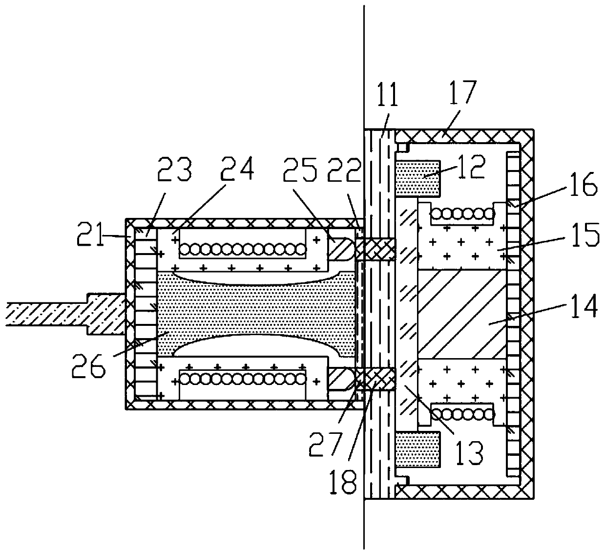
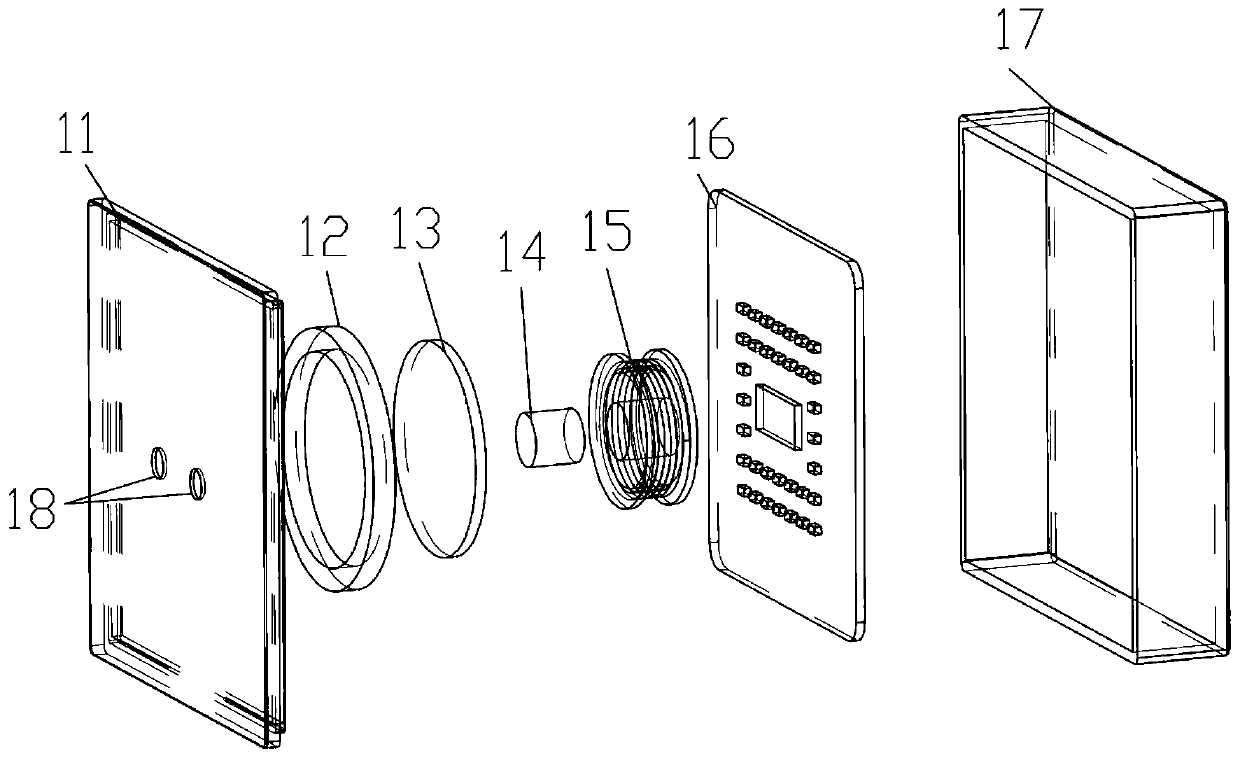
[0072] Embodiment 1. A non-hole socket based on electromagnetic induction and its matching conversion plug, such as Figure 1~7 As shown, the non-porous socket is connected to the mains, and the conversion plug is connected to the electrical equipment. In the process of taking power, the conversion plug is fixed on the surface of the non-porous socket by magnetic force, and the electrical equipment is powered by electromagnetic conversion.

[0073] The non-porous socket includes a socket housing. Such as figure 2 As shown, the socket housing is composed of a socket panel 11 and a socket shell 17, and the socket panel 11 and the socket shell 17 together form a socket cavity.

[0074] In this embodiment, the socket shell 17 adopts a metal shell, thereby effectively reducing electromagnetic interference, concentrating the electromagnetic field sending direction, and increasing electric power.

[0075] At least one light-transmitting hole I18 is provided on the socket panel 11, and the...


PUM


Abstract

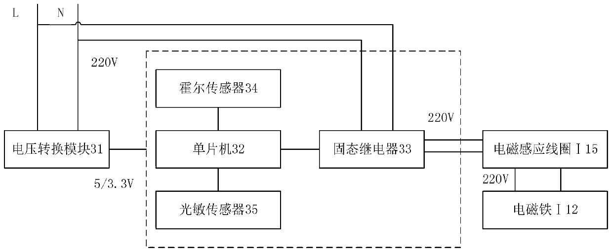
The invention provides a jack-free socket based on electromagnetic induction and a conversion plug matched with the jack-free socket. A socket cavity of the jack-free socket is internally provided with an electromagnet I, an electromagnetic induction coil I and a socket circuit board; the socket circuit board is composed of a voltage conversion module, a single chip microcomputer, a solid relay and a Hall sensor; an electric supply, the voltage conversion module, the single chip microcomputer, the solid relay, the electromagnetic induction coil I and the electromagnet I are connected in sequence; the solid relay is further connected with the electric supply; the Hall sensor is connected with the single chip microcomputer; a plug cavity is internally provided with a permanent magnet, a plugcircuit board, an electromagnetic induction coil II and an electromagnet II; the permanent magnet is installed on a plug panel; the electromagnetic induction coil II, an electromagnet II and electricequipment are connected with the plug circuit board respectively; the electromagnetic induction coil II and the electromagnet II are connected in series, and the electromagnetic induction coil II isused for supplying power for the electric equipment through the electromagnet II and the plug circuit board. The single chip microcomputer operates / sleeps through the Hall sensor, so that the energy consumption and cost are reduced.

Description

Technical field [0001] The invention relates to the field of sockets, in particular to a non-porous socket based on electromagnetic induction, and a conversion plug used in conjunction with the non-porous socket. Background technique [0002] The most important function of the socket is to provide continuous and stable voltage to electrical equipment. In the case of ensuring the normal operation of electrical equipment, human life safety is the most important thing to pay attention to. A socket with a hole will make it easy for children to access the socket without adults paying attention. It is more likely to be small under curiosity. Insertion of iron products causes electric shock. The sockets currently on the market are designed with holes: two-hole live wire, neutral and three-hole live wire, neutral and ground. It is precisely because of the open design with holes, which may lead to the risk of electric shock after contact during use, and accidents such as short-circuit a...

Claims


Application Information

Patent Timeline
Patent Type & Authority Applications(China)
IPC IPC(8): H01R13/502H01R13/52H01R13/62H01R13/658H01R13/66H01R13/703H01R13/713H01R13/717
Inventor 张华郭靖董智勇杨徽魏义坤
Owner 浙江理工大学上虞工业技术研究院有限公司
Learn More