

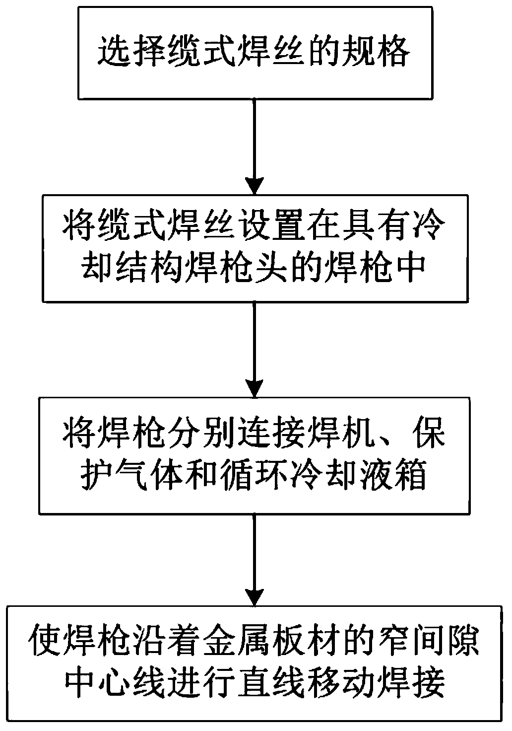
Cable welding wire narrow gap welding method, protective gas nozzle and welding gun
A cable-type welding wire and shielding gas technology, used in welding torches, cable-type welding wire narrow-gap welding, and shielding gas nozzle fields, can solve problems such as affecting welding efficiency and short service life of contact nozzles, so as to improve welding efficiency, improve production efficiency, The effect of improving the service life
- Summary
- Abstract
- Description
- Claims
- Application Information
AI Technical Summary
Problems solved by technology
Method used
Image

Examples
Example Embodiment
[0087] Example 1
[0088] The thickness of the steel plate in this embodiment is 80mm, the U-shaped groove is set, the gap width at the bottom of the groove is 10mm, and the 6+1 cable welding wire with a diameter of 2.4mm is used, the helix angle is 72°, and the shielding gas is 80% Ar+20%CO2, the welding parameters are shown in Table 2.
[0089] Table 2 Φ2.4mm (6+1) cable welding wire narrow gap gas shielded welding parameters
[0090]
[0091] After welding, the macroscopic metallography shows that the sidewalls are well fused.
Example Embodiment
[0092] Example 2
[0093] The thickness of the steel plate in this embodiment is 80mm, U-shaped grooves are set, the groove gap width is 15mm, and a (6+1) cable welding wire with a diameter of 2.4mm is used. The helix angle is 72° and the shielding gas is 80 %Ar+20%CO2, the welding parameters are shown in Table 3.
[0094] Table 3 Φ2.4mm (6+1) cable type welding wire narrow gap gas shielded welding parameters
[0095]
[0096] The macroscopic metallography shows that the sidewalls are well fused.
Example Embodiment
[0097] Example 3
[0098] The thickness of the steel plate in this embodiment is 80mm, the U-shaped groove is set, the gap width at the bottom of the groove is 10mm, and the (6+1) cable type welding wire with a diameter of 1.8mm is used, the helix angle is 72°, and the shielding gas is 80 %Ar+20%CO2, the welding parameters are shown in Table 4.
[0099] Table 4 Φ1.8mm6+1 cable welding wire narrow gap gas shielded welding parameters
[0100]
[0101] The macroscopic metallography shows that the sidewalls are well fused.
PUM
| Property | Measurement | Unit |
|---|---|---|
| Thickness | aaaaa | aaaaa |
| Diameter | aaaaa | aaaaa |
Abstract
Description
Claims
Application Information