Full-load new energy bus tail section frame

A new energy, full load-bearing technology, applied to vehicle components, electric power devices, substructures, etc., can solve problems such as insufficient strength, single structure of connecting plates, and easy to break, etc., to achieve convenient assembly, reliable structure, and reliable operation sexual effect

Active Publication Date: 2019-06-21
HUNAN CSR TIMES ELECTRIC VEHICLE
View PDF8 Cites 1 Cited by
  • Summary
  • Abstract
  • Description
  • Claims
  • Application Information

AI Technical Summary

Problems solved by technology

This technical solution solves the problem that the connecting plate connecting the rectangular beam at the rear section of the vehicle frame and the grooved beam at the rear section has a single structure, insufficient strength, and is prone to breakage
However, this structural design involves a girder-type frame structure, and does not involve a full-load frame structure, nor does it involve the installation structure of the powertrain, the installation structure of the electric air compressor, and the tow hook.

Method used


Image

  • Full-load new energy bus tail section frame
  • Full-load new energy bus tail section frame
  • Full-load new energy bus tail section frame

Examples


Embodiment Construction

[0018] The present invention will be described in further detail below in conjunction with the accompanying drawings and specific embodiments.

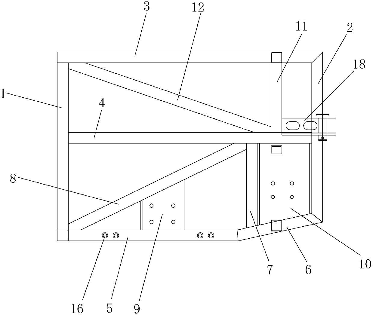
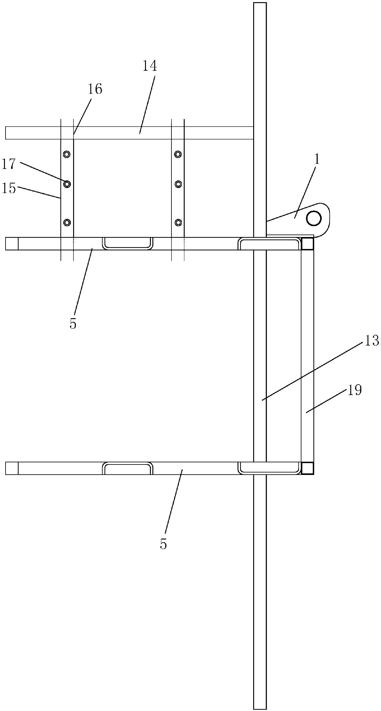
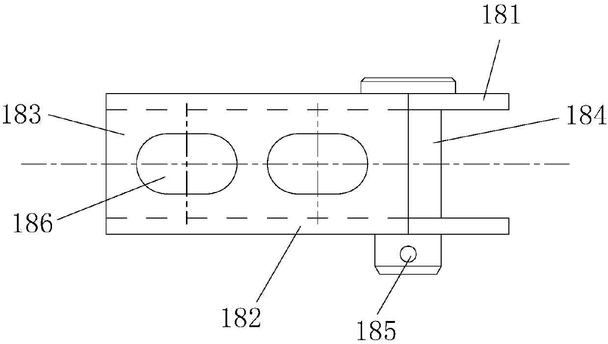
[0019] Figure 1 to Figure 4 An embodiment of the present invention is shown. The full-load new energy passenger car tail section frame of this embodiment includes the first column 1, the second column 2, the upper longitudinal beam 3, the middle longitudinal beam 4 and the first bottom longitudinal beam. Beam 5, the upper end of the first column 1 is flush with the second column 2, and the lower end of the first column 1 is lower than the second column 2, one end of the upper longitudinal beam 3 is fixedly connected to the upper end of the first column 1, and the other end is connected to the second column 2 The upper end is fixed, the middle longitudinal beam 4 is arranged under the upper longitudinal beam 3, and the two ends of the middle longitudinal beam 4 are fixedly connected with the first column 1 and the second column 2 resp...


PUM


Abstract

The invention provides a full-load new energy bus tail section frame. The full-load new energy bus tail section frame comprises a first stand column, a second stand column, an upper longitudinal beam,a middle longitudinal beam and a first bottom longitudinal beam, wherein the upper end of the first stand column is in flush with the second stand column, and the lower end of the first stand columnis lower; the upper longitudinal beam is fixedly connected with the first stand column and the second stand column; the middle longitudinal beam is arranged under the upper longitudinal beam; one endof the first bottom longitudinal beam is fixedly connected with the first stand column, and the other end of the first bottom longitudinal beam is fixedly connected with the second stand column through a transition beam; a first middle stand column is fixedly arranged between the middle longitudinal beam and the transition beam; a first diagonal bracing is fixedly arranged between a connection point of the first stand column and the first bottom longitudinal beam and a connection point of the first middle stand column and the middle longitudinal beam; a second middle stand column is fixedly arranged between the upper longitudinal beam and the middle longitudinal beam and is close to the second stand column; a second diagonal bracing is fixedly arranged between a connection point of the upper longitudinal beam and the first stand column and a connection point of the second middle stand column and the middle longitudinal beam; a driving motor suspending and mounting first partition plateis fixedly arranged between the first diagonal bracing and the first bottom longitudinal beam; a second partition plate is fixedly arranged among the middle longitudinal beam, the first middle standcolumn, the transition beam and the second stand column.

Description

technical field [0001] The invention relates to a new energy bus, in particular to a rear section frame of a fully loaded new energy bus. Background technique [0002] At present, the chassis frame of new energy buses is generally a full load-bearing structure, and the rear section of the frame involves powertrain installation, electric air compressor installation, and tow hook installation. The existing powertrain installation and electric air compressor installation structure are relatively complicated, and the layout of each structural part is unreasonable, resulting in inconvenient after-sales disassembly and maintenance, and poor reliability of powertrain operation. For example, the electric air compressor The installation is directly on the frame by welding. [0003] Patent document CN 204110149U discloses a connection structure between the rear section and the tail section of the vehicle frame, which includes: two connecting plates, two rear section rectangular beams...

Claims


Application Information

Patent Timeline
IPC IPC(8): B62D21/02B62D21/09B60K1/00
Inventor 龙爱军李泽波周宏涛王耀华李腾王星张彦斌陈煌熙陈诗库王文张琪
Owner HUNAN CSR TIMES ELECTRIC VEHICLE
Why Eureka
Try Eureka