Engine arm synchronous rotation structure and industrial unmanned aerial vehicle with same

A technology of synchronous rotation and arm, which is applied in the direction of affecting the air flow flowing through the surface of the aircraft, aircraft control, fuselage frame, etc., which can solve the waste of manual work time, large workload of folding, easy disassembly and assembly, and easy confusion of operators and other problems, to achieve the effect of reducing workload, improving efficiency, and reducing the workload of disassembly and assembly

Pending Publication Date: 2019-06-21
杜双昱
View PDF1 Cites 2 Cited by
  • Summary
  • Abstract
  • Description
  • Claims
  • Application Information

AI Technical Summary

Problems solved by technology

[0004] The present invention aims to solve the existing problems in the use of industrial drones in the prior art: the workload of folding this type of drone is relatively large, and if it involves a variety of drones with different specifications, it is easy to disassemble and assemble. Disassembly and assembly workers are easily confused, which is likely to cause technical problems such as waste of manual working time. A synchronous rotation structure of the machine arm and an industrial drone with this structure are provided.

Method used


Image

  • Engine arm synchronous rotation structure and industrial unmanned aerial vehicle with same
  • Engine arm synchronous rotation structure and industrial unmanned aerial vehicle with same
  • Engine arm synchronous rotation structure and industrial unmanned aerial vehicle with same

Examples


Embodiment Construction

[0094] The following will clearly and completely describe the technical solutions in the embodiments of the present invention with reference to the accompanying drawings in the embodiments of the present invention. Obviously, the described embodiments are only some, not all, embodiments of the present invention. Based on the embodiments of the present invention, all other embodiments obtained by persons of ordinary skill in the art without making creative efforts belong to the protection scope of the present invention.

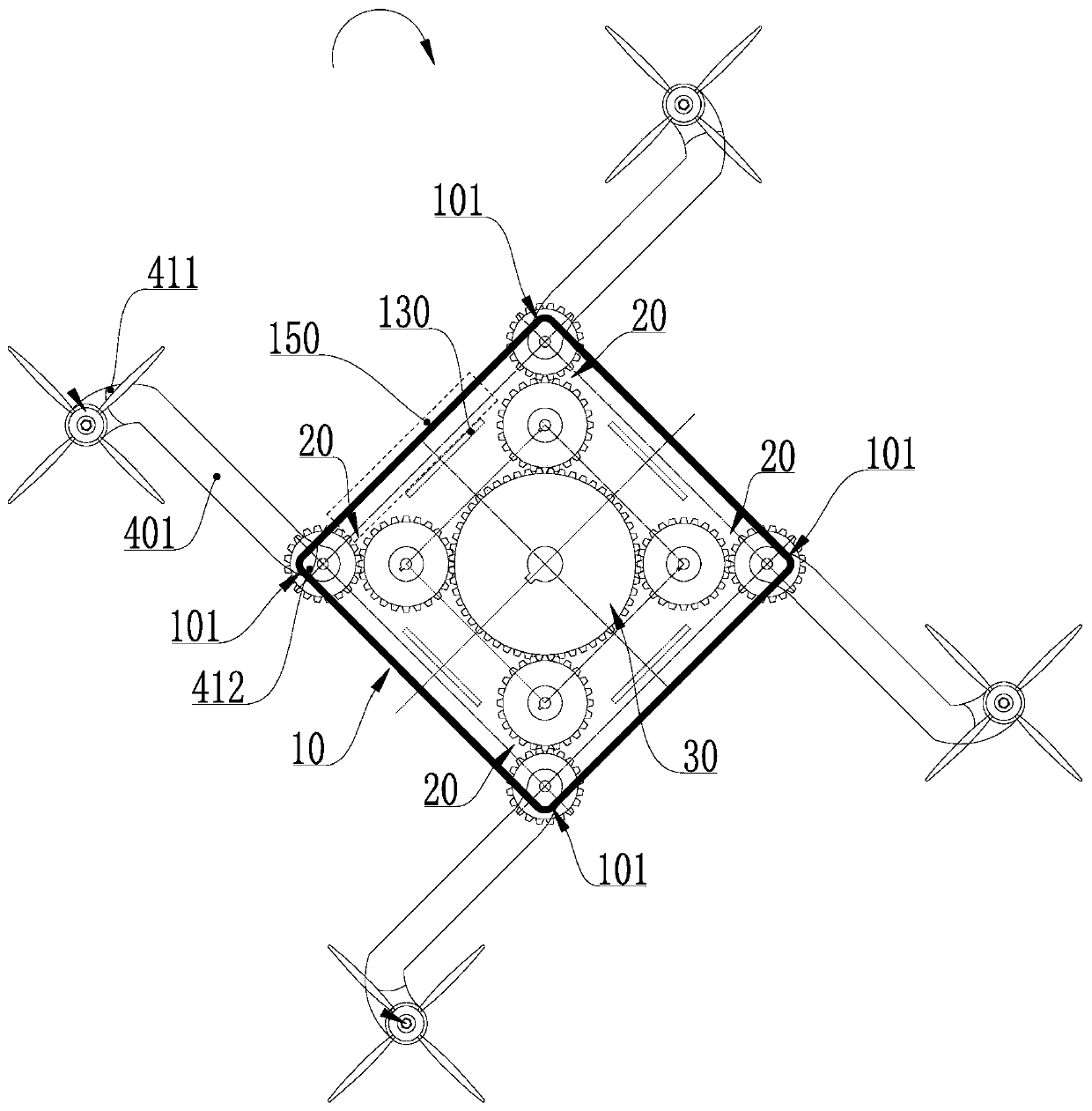
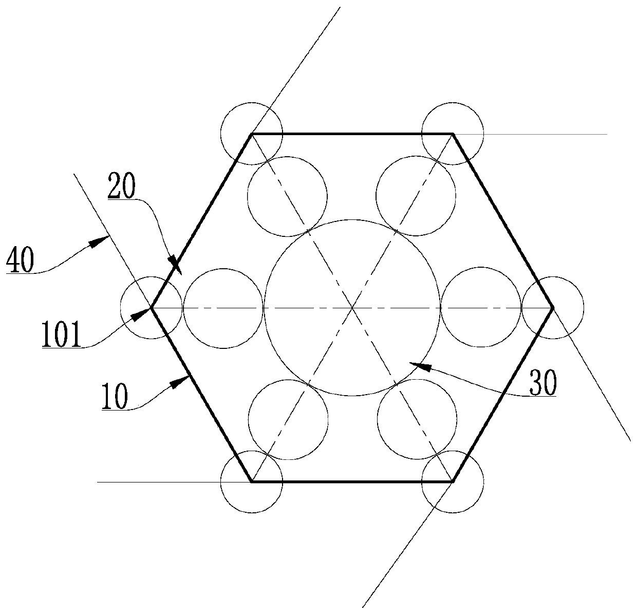
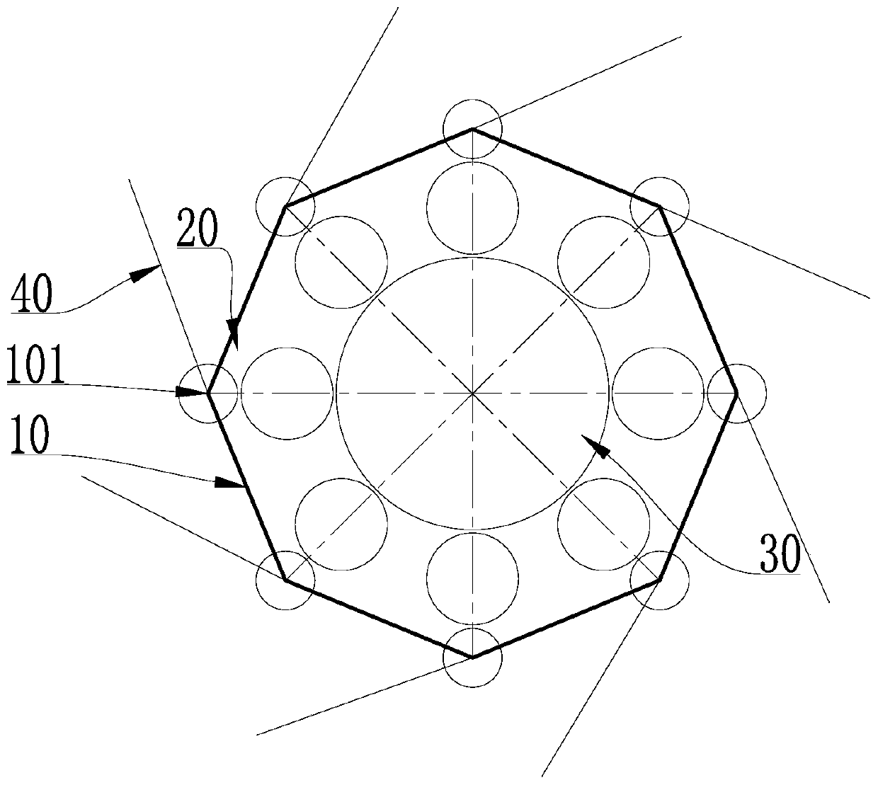
[0095] The present invention includes three embodiments, please refer to the attached Figure 1-3 As shown, the locking structure 50 can be applied in the above three embodiments at the same time, please refer to the following and the attached Figure 5 .

[0096] The technical problem to be solved by the present invention is to achieve three effects. First, it needs to be able to achieve a foldable effect, which is used to reduce the volume of the entire dro...


PUM


Abstract

The invention is an engine arm synchronous rotation structure and an industrial unmanned aerial vehicle with the engine arm synchronous rotation structure, relates to the technical field of industrialunmanned aerial vehicles, and solves the technical problem that the disassembly of the unmanned aerial vehicle wastes operation time. The engine arm synchronous rotation structure comprises a frame body structure, auxiliary transmission mechanisms, a main transmission mechanism, engine arm bodies, and a locking mechanism; the main transmission mechanism is arranged in the middle of the frame bodystructure and is used for simultaneously controlling all the auxiliary transmission mechanisms to rotate in a driving manner; one ends of the engine arm bodies are used for connecting rotor wings, and the other ends are fixedly connected with a group of auxiliary transmission mechanisms; the frame body structure and the engine arm bodies have a folding state and an unfolding state, and the locking mechanism is used for keeping the frame body structure and the engine arm bodies in the folding state or the unfolding state. The engine arm synchronous rotation structure and the industrial unmanned aerial vehicle with the engine arm synchronous rotation structure have the advantages that the operation is fast, no complicated disassembly steps are needed, the operation time is saved, and convenient accommodation and storage are realized.

Description

technical field [0001] The invention relates to the technical field of industrial drones, in particular to a synchronous rotation structure of machine arms and an industrial drone with the structure. Background technique [0002] Under the current trend, industrial drones have become an emerging development direction in the field of drone technology. The main reason for their becoming a hot spot is that they have a large base of consumer customers and require a wide range of technical fields, such as agricultural plant protection, power detection, police security, etc. The demand for industrial-grade drones is the most prominent in the field. [0003] With the application number CN201710936039.8, the application date is October 10, 2017, the publication number is CN107697267A, and the Chinese invention patent application titled "A UAV Rotor Folding Structure and UAV" discloses a A kind of unmanned aerial vehicle rotor folding structure and unmanned aerial vehicle, its techn...

Claims


Application Information

Patent Timeline
Patent Type & Authority Applications(China)
IPC IPC(8): B64C1/06B64C1/30
Inventor 杜双昱
Owner 杜双昱
Why Eureka
Try Eureka