A fixture device

A jig device and jig technology, applied in metal material coating process, vacuum evaporation coating, coating, etc., can solve the problem of reducing the effective film forming area of ​​vapor deposition equipment, increasing the area of ​​the opaque area of ​​the floating mask, Fixtures are prone to problems such as film coating problems, achieving the effects of simple disassembly, improved production efficiency, and accurate positioning

Active Publication Date: 2020-11-06
NANJING CEC PANDA LCD TECH
View PDF9 Cites 0 Cited by
  • Summary
  • Abstract
  • Description
  • Claims
  • Application Information

AI Technical Summary

Problems solved by technology

During the process of sputtering film formation of the fixture device, not only the fixture 3 is prone to film coating problems, but also the support part 2 will also cause film film problems, which will also cause film formation problems on the panel
[0006] It takes three minutes for each fixture device to be removed, installed and debugged. It is necessary to remove the base, support part and fixture at the same time, and replace the fixture device on the entire substrate support tray. The time is very long, and each substrate support tray The two fixtures need to work together, and the height difference between the fixtures will cause problems such as fragmentation of the panel
[0007] When the existing fixture device is sputtering into a film, the fixture device needs to be protected by a floating mask, so the fixture device needs to be under the opaque area of ​​the floating mask, thus increasing the opacity of the floating mask. The area of ​​the light-transmitting area reduces the effective film-forming area of ​​the vapor deposition equipment

Method used


Image

  • A fixture device
  • A fixture device
  • A fixture device

Examples


Embodiment

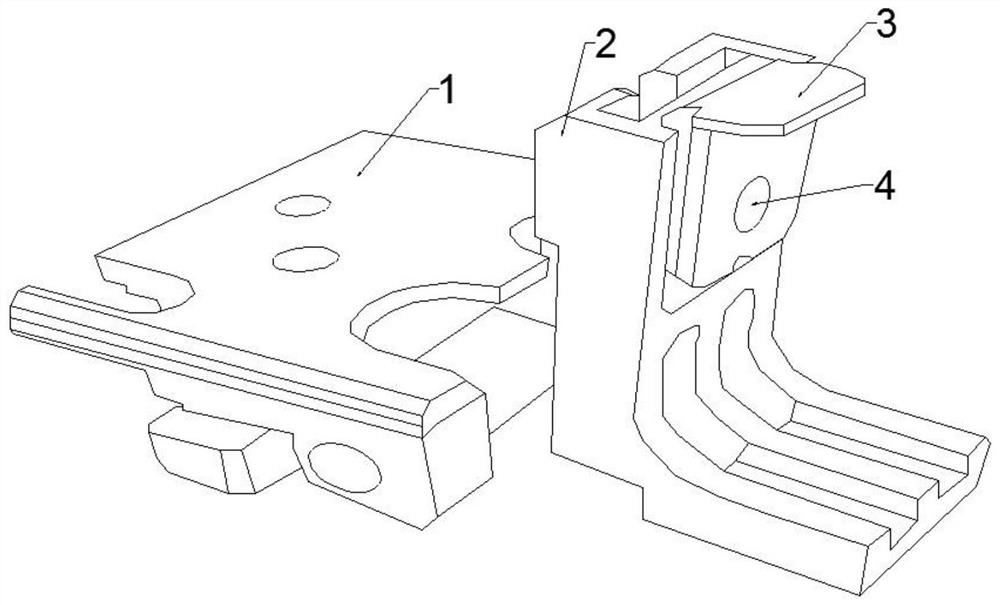
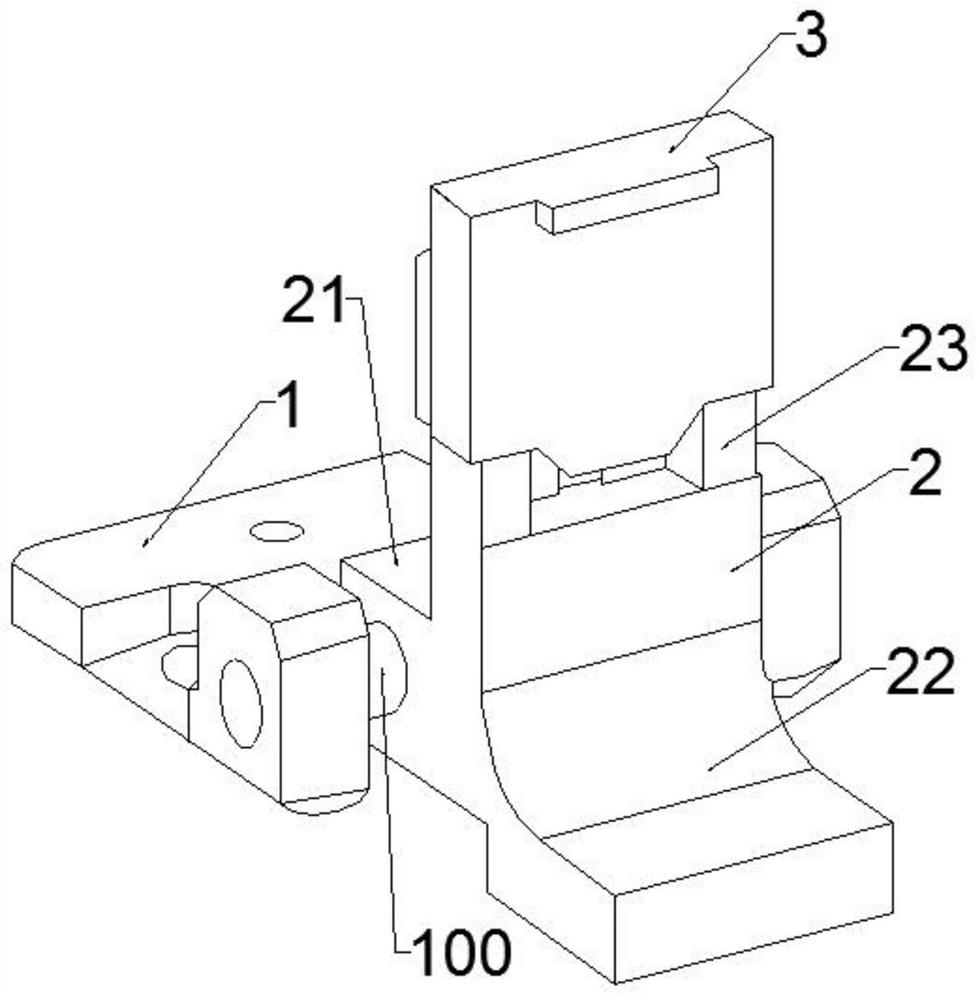
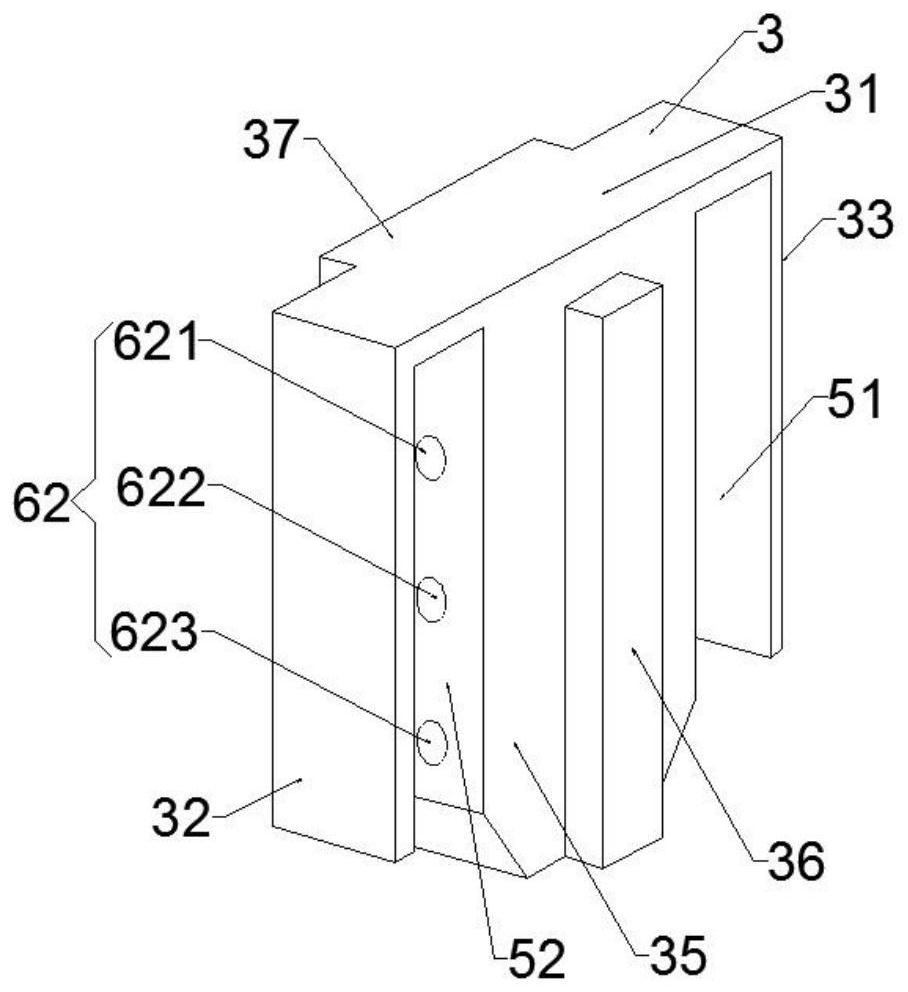
[0029] Such as Figure 2 to Figure 4 Shown is a schematic structural view of an embodiment of the fixture device of the present invention. This embodiment provides a fixture device, including: a base 1 connected to a substrate support tray (not shown in the figure), a support part 2 connected to the base 1 and The clamp 3 is set on the upper end of the support part 2. The support part 2 includes a first connecting body 21 at one end, a second supporting body 22 extending in the opposite direction to the first connecting body 21, and a third connecting body 23 at the other end. A connecting shaft 100 passes through the first connecting body 22. A connecting body 21 is fixedly connected to the base 1; the second supporting body 22 and the third connecting body 23 are L-shaped, and the second supporting body 22 is used to support the substrate; the clamp 3 is set on the end of the third connecting body 23 part, and the clamp 3 covers the top of the third connecting body 23, and ...


PUM


Abstract

The invention discloses a clamp device, and belongs to the field of panel manufacturing clamps. The clamp device comprises a base and a support portion connected with the base; the clamp device further comprises a clamp arranged at the upper end of the support portion in a sleeving mode; the support portion comprises a first connecting body which is located at one end of the support portion and connected with the base, a second support body extending in the direction opposite to the first connecting body, and a third connecting body located at the other end of the support portion; the clamp isarranged at the end of the third connecting body in a sleeving mode; and the clamp covers the top of the third connecting body. By wrapping the support portion with the clamp, the clamp is coated with a film while the support portion is not coated with a film in the sputtering coating process, only the clamp part needs to be replaced during replacement, meanwhile, the connection mode of the clampand the support portion is changed, thus, the operation of the clamp is more convenient to operate and time-saving during replacement, and the production efficiency is improved.

Description

technical field [0001] The invention belongs to the technical field of clamps, in particular to a clamp device. [0002] technical background [0003] In the manufacturing process of liquid crystal display panels, especially in the manufacturing process of array substrates, physical vapor deposition is an important step. At this stage, a physical vapor deposition equipment includes six substrate support trays, and each substrate support tray is equipped with Twenty-four to twenty-six clamping devices, the substrate support tray carries the glass substrate to complete the coating process, and the clamping device plays the role of fixing the glass substrate in this process. [0004] In the process of sputtering and film formation, the fixture device will also be covered with film, so it needs to be replaced regularly to prevent the peeling off of the film on the surface of the fixture device during the sputter film formation process of the substrate, which will cause foreign ma...

Claims


Application Information

Patent Timeline
Patent Type & Authority Patents(China)
IPC IPC(8): C23C14/50C23C14/34
Inventor 方兴杨旭卜长飞
Owner NANJING CEC PANDA LCD TECH
Why Eureka
Try Eureka