Life cabin escape system

An escape system and life technology, applied in the field of escape systems, can solve problems such as slow descending speed, and achieve the effects of reducing power consumption, increasing length, and increasing escape speed.

Active Publication Date: 2019-06-21
黄亿禾
View PDF12 Cites 1 Cited by
  • Summary
  • Abstract
  • Description
  • Claims
  • Application Information

AI Technical Summary

Problems solved by technology

However, relatively small escape products are often difficult to give people enough courage and a sense of security. Larger escape products often fall at a slower speed in order to ensure safety and stability, and how to solve the problem of running without electricity is also a consideration in research and development. important factor

Method used


Image

  • Life cabin escape system
  • Life cabin escape system
  • Life cabin escape system

Examples


Embodiment 1

[0029] Such as Figure 4 As shown, the escape passage in this embodiment is vertical; the vertical escape passage has the fastest escape speed, but in order to ensure the safety of the personnel in the escape cabin during the escape process, a safety valve is provided at the bottom of the vertical part of the escape passage. Air cushion; And present embodiment is not suitable for high-floor escape use.

Embodiment 2

[0031] Such as Figure 5As shown, the escape passage in this embodiment is inclined; compared with Embodiment 1, the safety of this embodiment is higher, and in order to further enhance the safety of this embodiment, a silica gel pad can be laid in the escape passage to prevent escape The outer surface of the cabin is provided with a thin layer of rubber to increase the friction of the escape cabin when it rolls, thereby reducing the speed of the escape cabin and enhancing safety; it can also extend the length of the escape passage, reduce the slope of the escape passage, and increase the slowness to ensure escape. It is safe and can directly transport escaped people to an open place far away from danger.

Embodiment 3

[0033] Such as Figure 6 As shown, the escape passage in the present embodiment is spiral, and the present embodiment is safer than the first embodiment, and saves more floor space than the second embodiment; the spiral escape passage can effectively slow down the falling speed of the escape cabin. To further enhance safety, silica gel pads can be laid in the escape passage, and a thin rubber layer is provided on the outer surface of the escape cabin to increase the friction force when the escape cabin rolls, reduce the speed of the escape cabin, and enhance safety.

[0034] Compared with the prior art, the present invention has the following advantages:

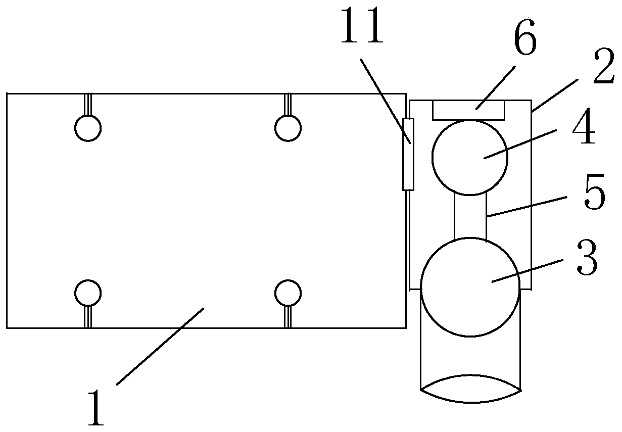
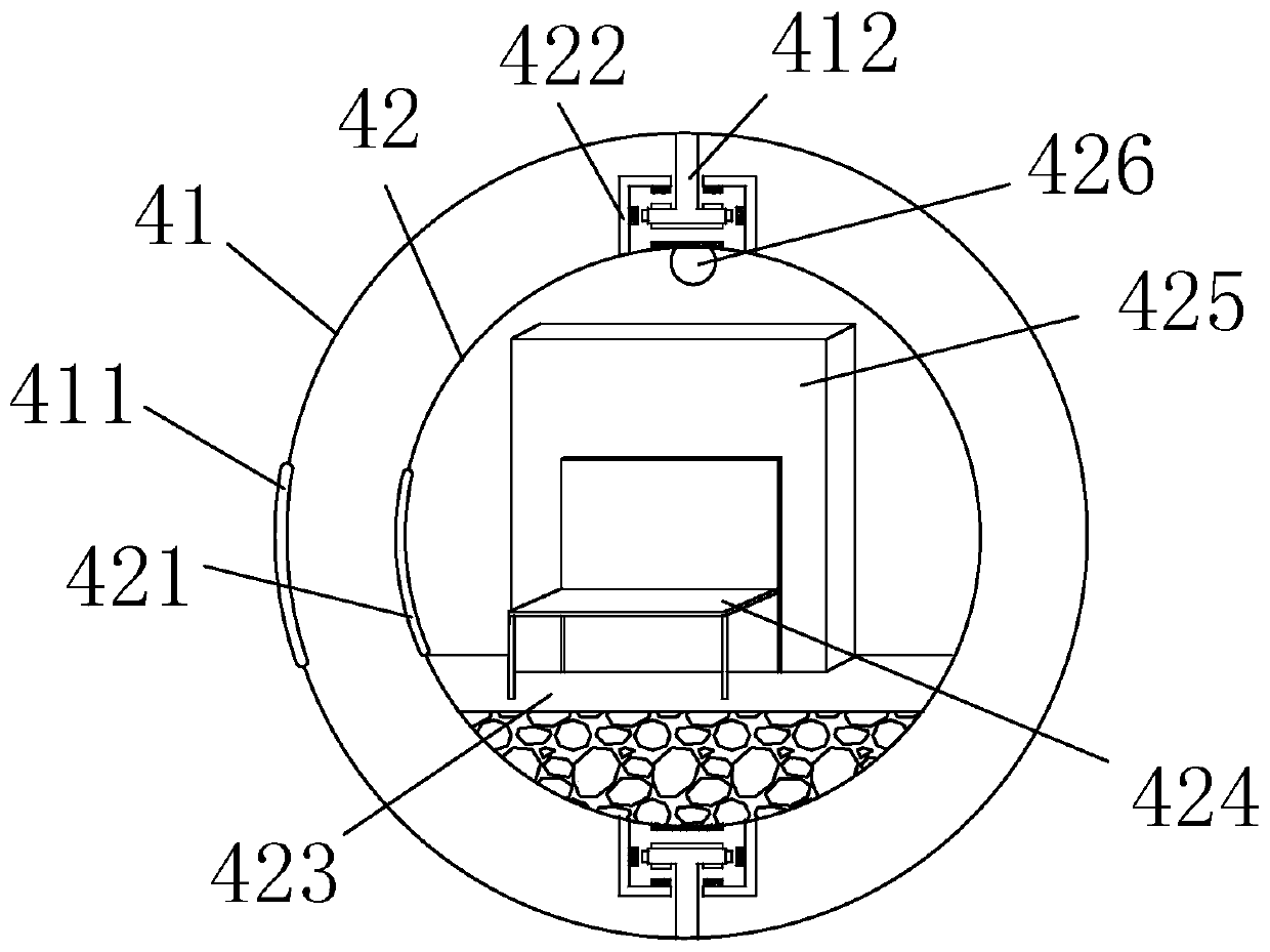
[0035] a. The spherical escape cabin can move quickly without professional training, and can accommodate many people at the same time, increasing the escape speed;

[0036] b. There is storage space for food and drinking water in the escape cabin, which can ensure that the escaped personnel have sufficient food sources afte...


PUM


Abstract

The invention discloses a life cabin escape system which comprises a room, an escape chamber and an escape channel. The room communicates with the escape chamber through a room door; the escape channel is arranged on the front side of the escape chamber, an escape opening is formed in the escape channel, and the escape channel communicates with the escape chamber through the escape opening. The lower end of the escape channel extends to the ground; an escape cabin is arranged in the escape chamber; a rail extending to the escape opening is arranged at the bottom of the escape cabin, and an escape cabin ejector is arranged on the wall of the escape chamber on the back face of the escape cabin; and the escape cabin can run to the escape opening along the rail under the action of the escape cabin ejector, enters the escape channel from the escape opening and then reaches the ground through the escape channel. The spherical escape cabin can rapidly move, and the escape speed is increased;it can be guaranteed that escape people have sufficient food sources after escaping; due to the self-rolling characteristic of the escape cabin, the power consumption during escape can be reduced; andthe system can be applied to various escape situations such as fire disasters and earthquakes.

Description

technical field [0001] The invention relates to an escape system, in particular to a life cabin escape system. Background technique [0002] Accidents are unavoidable in daily life. In the face of sudden disasters, how people can ensure fast and efficient escape has always been a hot spot of concern. At present, there are many studies on escape devices for high-rise fires. The escape products are mainly compact and convenient. It is a sales hotspot, and basically achieves the functional characteristics of quick escape anytime, anywhere. However, relatively small escape products are often difficult to give people enough courage and a sense of security. Larger escape products often fall at a slower speed in order to ensure safety and stability, and how to solve the problem of running without electricity is also a consideration in research and development. important factor. Contents of the invention [0003] In order to solve the deficiencies in the above-mentioned technolo...

Claims


Application Information

Patent Timeline
Patent Type & Authority Applications(China)
IPC IPC(8): E21F11/00
Inventor 黄亿禾龚春美黄雪兵
Owner 黄亿禾
Why Eureka
Try Eureka