
Microobjective numerical aperture measurement method based on diffraction grating

A technology of microscopic objective lens and numerical aperture, which is applied in the field of optical detection, and can solve problems such as large errors in measurement results, cumbersome operation, and single measurement standard

Inactive Publication Date: 2019-06-21
BEIHANG UNIV
View PDF9 Cites 0 Cited by
  • Summary
  • Abstract
  • Description
  • Claims
  • Application Information

AI Technical Summary

Problems solved by technology

[0006] The traditional system for measuring the numerical aperture of the microscope objective lens is cumbersome to operate; the existing method has a single measurement standard, and the measurement results are prone to large errors

Method used


Image

  • Microobjective numerical aperture measurement method based on diffraction grating
  • Microobjective numerical aperture measurement method based on diffraction grating
  • Microobjective numerical aperture measurement method based on diffraction grating

Examples


specific Embodiment approach 1

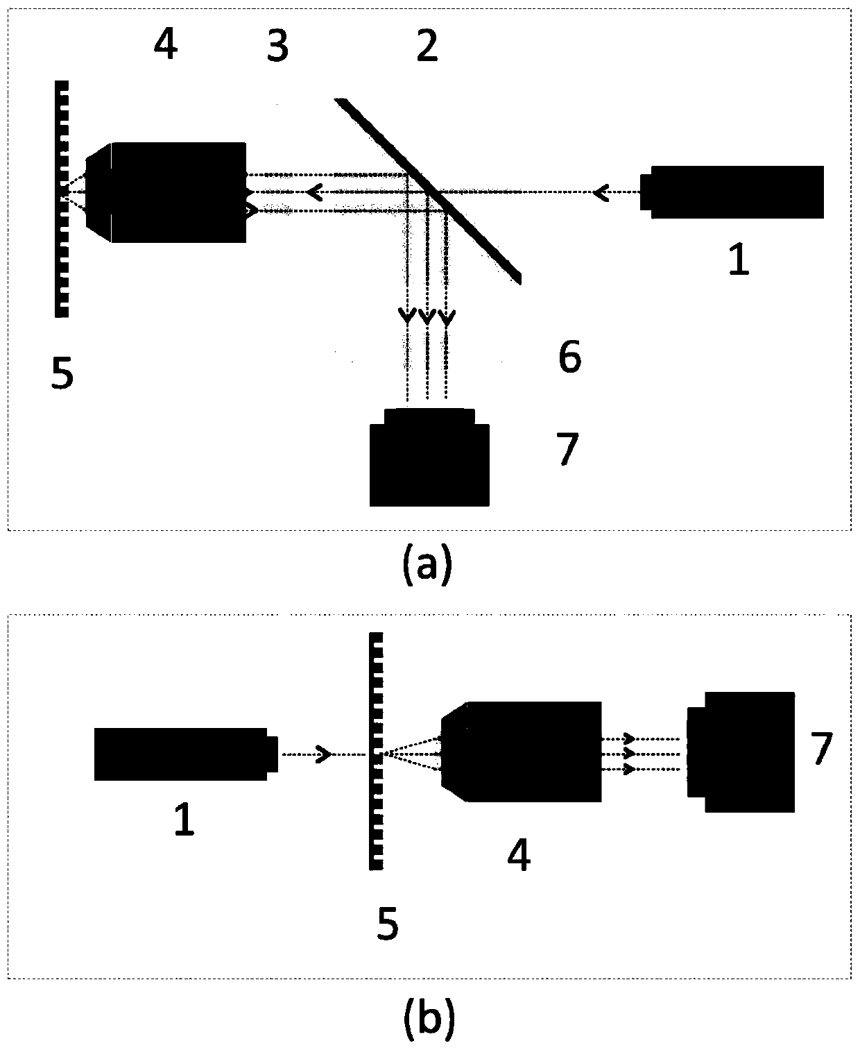
[0026] Specific Embodiment 1: Combining image 3 The optical path in (a) illustrates the present embodiment, and now the diffraction grating (5) is a reflective grating, and a kind of microscopic objective lens numerical aperture method based on the diffraction grating described in the present embodiment, the purpose is to pass the diffraction effect and display The imaging effect of the micro-objective lens obtains the numerical aperture of the micro-objective lens to be tested, and it comprises: collimated illumination light source (1); Beamsplitter prism (2); Lens 1 (3); Microscopic objective lens to be measured (4); Diffraction grating ( 5); lens 2 (6); image sensor (7). The collimated light beam emitted by the collimated illumination source (1) passes through the dichroic prism (2) and the lens 1 (3), and after being converged by the microscopic objective lens (4) to be measured and irradiated on the diffraction grating (5), the diffraction After the light is reflected a...

specific Embodiment approach 2

[0031] Specific Embodiment 2: Combining image 3 The optical path in (b) illustrates the present embodiment, and now the diffraction grating (5) is a transmissive grating, and a kind of method for the numerical aperture of the microscopic objective lens based on the diffraction grating described in the present embodiment, the purpose is to pass the diffraction effect and display The imaging function of the micro-objective lens obtains the numerical aperture of the micro-objective lens to be tested, which includes: a collimated illumination light source (1); a diffraction grating (5); a micro-objective lens to be tested (5); and an image sensor (7). After the collimated light beam emitted by the collimated illumination source (1) is irradiated on the diffraction grating (5), the generated diffracted light passes through the microscopic objective lens (4) to be tested to obtain multi-level diffraction fringes on the image sensor (7), The numerical aperture of the microscopic obj...


PUM


Abstract

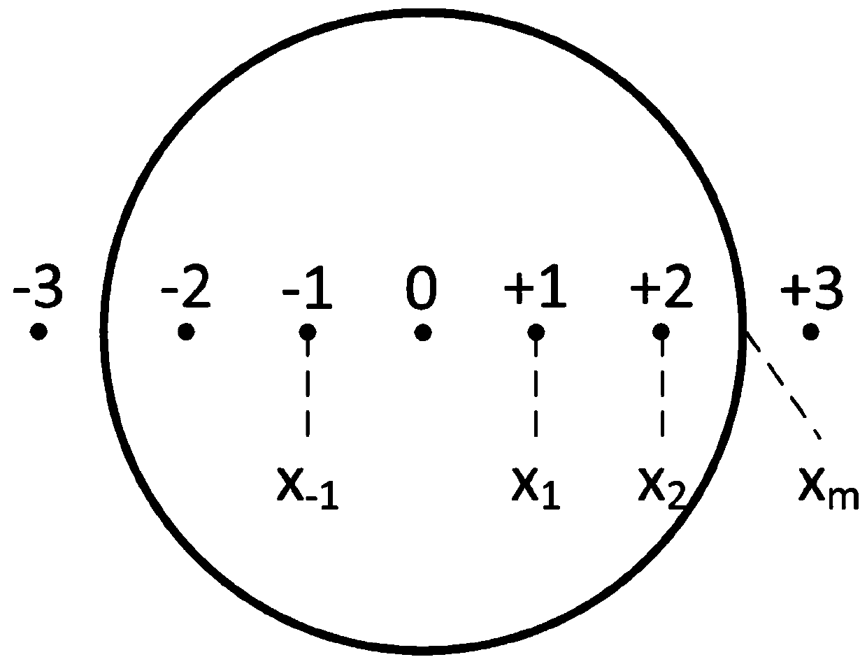
The present invention provides a microobjective numerical aperture measurement method based on diffraction grating, and relates to the field of optical detection, especially to measurement of a microobjective numerical aperture. The method comprises measurement for the numerical apertures of liquid immersion and solid immersion microobjectives. The problem is solved that the operation is tedious when the microobjective numerical aperture is measured in the prior art, and the measurement precision can be further improved. The method comprises the steps of: allowing a light beam to generate multiple-slit diffraction after passing through a diffraction grating, and passing through the microobjective to observe diffraction fringes at the back focal plane of the microobjective. The position ofthe diffraction fringe and the position of the view field boundary of the back focal plane are determined to calculate and obtain the microobjective numerical aperture according to the function relation between position of the diffraction fringe and the position of the view field boundary of the back focal plane and the microobjective numerical aperture. A computer is employed to identify the diffraction image obtained on the image sensor to achieve high-precision measurement of the microobjective numerical aperture.

Description

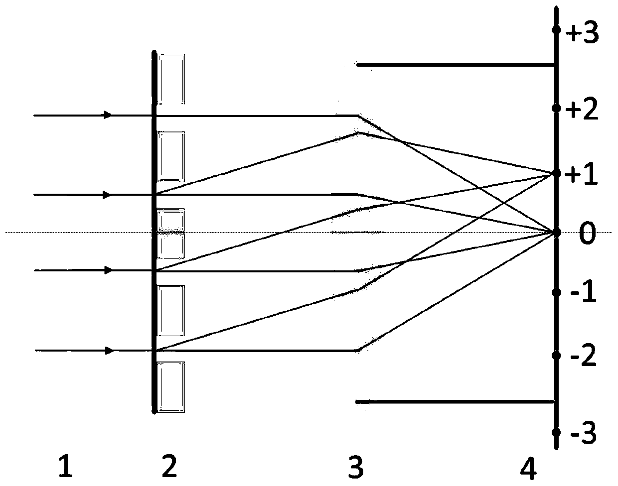
technical field [0001] The invention relates to the field of optical detection, in particular to a method for measuring the numerical aperture of a microscopic objective lens based on a diffraction grating. Background technique [0002] The core component of the microscopic system is the microscopic objective lens. The performance of the entire microscopic system is determined by the microscopic objective lens, and the numerical aperture is an important parameter to judge the performance of the microscopic objective lens (resolution, focal depth, brightness, etc.). A good numerical aperture The measurement method is of great significance to the optical-mechanical design and integration process of the microscope objective lens. [0003] At present, the numerical aperture of the objective lens is mainly measured by using a numerical aperture meter. Human eyes are mainly used for observation during measurement, and the intersection point of the reticle on the numerical aperture...

Claims


Application Information

Patent Timeline
IPC IPC(8): G01M11/00
Inventor 张蓓肖天宇王希奇闫鹏胡庆雷
Owner BEIHANG UNIV
Learn More