Fluid module pressure control circuit based on flow cytometer

A flow cytometer and pressure control technology, applied in the electronic field, can solve problems such as poor stability, unstable pressure control, and high overall cost, and achieve good cost-effectiveness, stable pressure control, and avoid control circuits and instability The effect of the control loop

Pending Publication Date: 2019-06-21
无锡厦泰生物科技有限公司
View PDF11 Cites 1 Cited by
  • Summary
  • Abstract
  • Description
  • Claims
  • Application Information

AI Technical Summary

Problems solved by technology

[0002] At present, there are many pressure control circuits in the fluid module of the flow cytometer. These control circuits are relatively complicated, and the stability is relatively poor, which is prone to unstable pressure control or high overall costs.

Method used


Image

  • Fluid module pressure control circuit based on flow cytometer
  • Fluid module pressure control circuit based on flow cytometer
  • Fluid module pressure control circuit based on flow cytometer

Examples


Embodiment Construction

[0024] In order to more clearly illustrate the embodiments of the present invention or the technical solutions in the prior art, the specific implementation manners of the present invention will be described below with reference to the accompanying drawings. Obviously, the accompanying drawings in the following description are only some embodiments of the present invention, and those skilled in the art can obtain other accompanying drawings based on these drawings and obtain other implementations.

[0025] In order to make the drawing concise, the parts related to the present invention are only schematically shown in each drawing, and they do not represent the actual structure of the product.

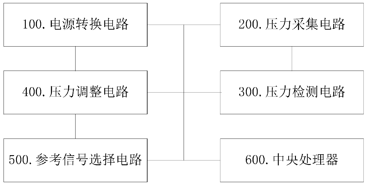
[0026] refer to figure 1 Shown is a schematic diagram of an embodiment of a pressure control circuit based on a fluid module of a flow cytometer provided by the present invention; the pressure control circuit of the fluid module of a flow cytometer includes: a power conversion circuit ...


PUM


Abstract

The invention discloses a fluid module pressure control circuit based on a flow cytometer. The pressure control circuit includes a power conversion circuit, a pressure collecting circuit, a pressure detecting circuit, a pressure adjusting circuit and a reference signal selecting circuit, wherein the pressure collecting circuit and the pressure adjusting circuit are in communication connection withan input end of the pressure detecting circuit, an output end of the pressure detecting circuit is in communication connection with the pressure adjusting circuit, after the pressure control circuitis powered by the power conversion circuit, a pressure signal of the sheath liquid flow collected by the pressure collecting circuit is inputted to the pressure detecting circuit and compared with a reference pressure signal provided by the reference signal selecting circuit, generated pressure difference is further outputted, the pressure difference outputted by the pressure detecting circuit isinputted to the pressure adjusting circuit, and the flow of the sheath liquid flowing through a pressure control valve is adjusted by the pressure adjusting circuit according to the magnitude of the pressure difference, and thereby control of the flow pressure of the sheath liquid is realized.

Description

technical field [0001] The invention relates to the field of electronic technology, in particular to a pressure control circuit of a fluid module based on a flow cytometer. Background technique [0002] At present, there are many pressure control circuits in the fluid module of the flow cytometer. These control circuits are relatively complicated, and the stability is relatively poor, which is prone to unstable pressure control or high overall costs. [0003] Therefore, based on the above existing technical problems, the present invention provides a technical solution to solve the above technical problems. Contents of the invention [0004] The purpose of the present invention is to provide a pressure control circuit based on a fluid module of a flow cytometer, which uses a pressure sensor to detect the actual operating sheath fluid pressure and converts it into a corresponding voltage, which is compared and amplified by a comparator with a reference voltage , the output ...

Claims


Application Information

Patent Timeline
Patent Type & Authority Applications(China)
IPC IPC(8): G01N15/14G01N15/10G05D16/20G05F1/46
Inventor 冉懋学
Owner 无锡厦泰生物科技有限公司
Why Eureka
Try Eureka