Self-operated regulating valve for boiler gas pipeline

A technology for self-operated regulating valves and gas pipelines, which is applied in the direction of valve lifts, valve details, and valve devices. It can solve problems such as unstable gas pressure, rising downstream pipeline pressure, and potential safety hazards, and achieve rapid and real-time response speed and stability. The effect of pressure control

Pending Publication Date: 2020-05-08
GUANGDONG INSPECTION & RES INST OF SPECIAL EQUIP ZHUHAI INSPECTION INST
View PDF0 Cites 0 Cited by
  • Summary
  • Abstract
  • Description
  • Claims
  • Application Information

AI Technical Summary

Problems solved by technology

When the existing self-operated regulating valve is used in the boiler gas pipeline, due to the mechanical inertia of the regulating spring, tray and other components, the response speed is slower than that of the boiler burner. When the boiler burner is closed and the boiler stops burning, the valve core usually delays for about 3s In this process, the gas will continue to enter the downstream pipeline of the self-operated regulating valve, causing the pressure of the downstream pipeline to rise instantaneously, which brings certain safety hazards. During the normal operation of the boiler, the upstream gas of the self-operated regulating valve The coupling of pressure fluctuations and the hysteresis of self-operated regulating valve adjustment will bring huge unstable factors to the adjustment of gas pressure

Method used


Image

  • Self-operated regulating valve for boiler gas pipeline
  • Self-operated regulating valve for boiler gas pipeline
  • Self-operated regulating valve for boiler gas pipeline

Examples


Embodiment Construction

[0019] In order to enable those skilled in the art to better understand the technical solutions of the present invention, the present invention will be further described in detail below in conjunction with specific examples. The embodiments described below are exemplary only for explaining the present invention and should not be construed as limiting the present invention. If no specific technique or condition is indicated in the examples, it shall be carried out according to the technique or condition described in the literature in this field or according to the product specification.

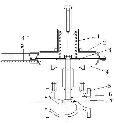
[0020] figure 1 It is a prior art in the art, and for a specific description, refer to the background technology section.

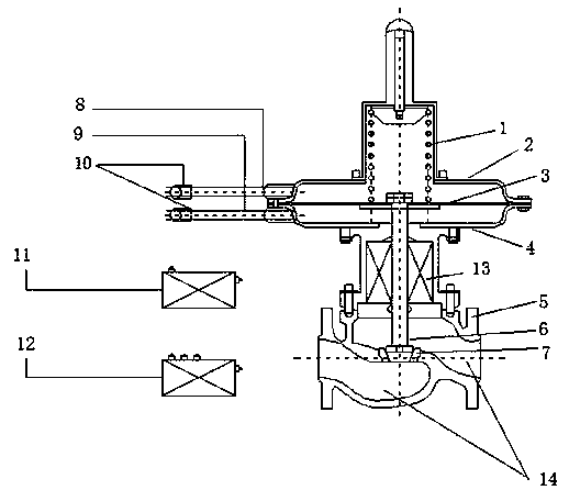
[0021] figure 2 It is a structural schematic diagram of the regulating valve of the present invention, such as figure 2 As shown, the self-operated regulating valve applied to the boiler gas pipeline provided by the present invention, in addition to the regulating sp...


PUM


Abstract

The invention relates to a self-operated regulating valve for a boiler gas pipeline. The self-operated regulating valve comprises a main body, an electromagnetic induction module, a piezoelectric transmitter, a controller and a pulse current generator, and is characterized in that an electromagnetic induction coil, the piezoelectric transmitter, the pulse current generator and the controller are additionally arranged on the existing self-operated regulating valve; and when a boiler combustor is closed or the upstream/downstream pipeline pressure of the self-operated regulating valve fluctuates, axial pulse electromagnetic force is applied to a valve element through the electromagnetic induction coil, and the response speed and the regulating stability of the regulating valve are improved.

Description

technical field [0001] The invention relates to the field of mechanical equipment, in particular to a self-operated regulating valve for boiler gas pipelines. Background technique [0002] At present, as an important device for pressure control, self-operated regulating valves are widely used in gas pipelines, including boiler gas pipelines. The structure of the existing self-operated regulating valve is as follows: figure 1 shown. The existing self-operated regulating valve relies on the resultant force generated by the regulating spring, the pressure pipe before the valve, the pressure pipe after the valve, the tray and other components to change the relative position of the valve core, thereby controlling the flow of gas. When the existing self-operated regulating valve is used in the boiler gas pipeline, due to the mechanical inertia of the regulating spring, tray and other components, the response speed is slower than that of the boiler burner. When the boiler burner ...

Claims


Application Information

Patent Timeline
Patent Type & Authority Applications(China)
IPC IPC(8): F16K31/06F16K1/00
CPCF16K1/00F16K31/0655F16K31/0675
Inventor 周道曦陈绍斌黄桂林杨剑赟杜明坤李青松马冰洋高峰孙吉
Owner GUANGDONG INSPECTION & RES INST OF SPECIAL EQUIP ZHUHAI INSPECTION INST
Why Eureka
Try Eureka