Laser emitting device for laser radar, and laser radar

A technology of laser emission and laser radar, which is applied in the direction of measuring devices, electromagnetic wave re-radiation, and utilization of re-radiation, can solve problems such as inconvenient operation, low space utilization rate, unfavorable cost saving, etc., to avoid damage and solve heat generation big effect

Active Publication Date: 2019-06-21
HESAI TECH CO LTD
View PDF15 Cites 7 Cited by
  • Summary
  • Abstract
  • Description
  • Claims
  • Application Information

AI Technical Summary

Problems solved by technology

[0003] However, in the current lidar, there are still the following problems: first, multiple lasers are directly installed on the transmitting circuit board, the N pole of the laser faces downward, and the P pole faces upward. This structure is not conducive to heat dissipation; secondly, in order to realize Higher number of lines and higher angular resolution, adding more rows of lasers in the horizontal direction to achieve angle encryption and increase the number of lines, which will lead to low space utilization in the system, and the focal plane position is particularly crowded. The heat is large, and the heat is difficult to export and other problems; thirdly, in the current laser radar, it is necessary to align the optical fiber with the laser first, and then fix the optical fiber on the optical fiber fixture, which requires manual adjustment during use, resulting in poor operation. Convenience, and not conducive to saving costs

Method used


Image

  • Laser emitting device for laser radar, and laser radar
  • Laser emitting device for laser radar, and laser radar
  • Laser emitting device for laser radar, and laser radar

Examples


Embodiment Construction

[0027] The making and using of the embodiments are discussed in detail below. It should be understood, however, that the specific embodiments discussed are merely illustrative of specific ways to make and use the invention, and do not limit the scope of the invention. The expression of the structural position of each component such as up, down, top, bottom, etc. in the description is not absolute, but relative. These directional expressions are appropriate when the various components are arranged as shown in the drawings, but when the positions of the various components in the drawings are changed, these directional expressions are also changed accordingly.

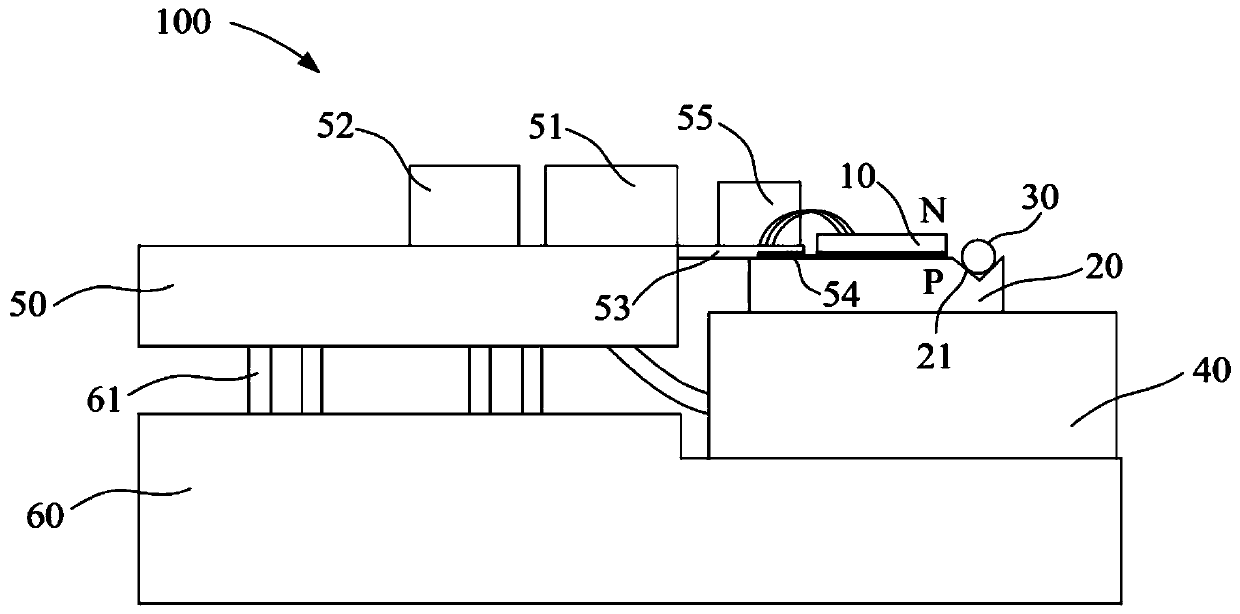
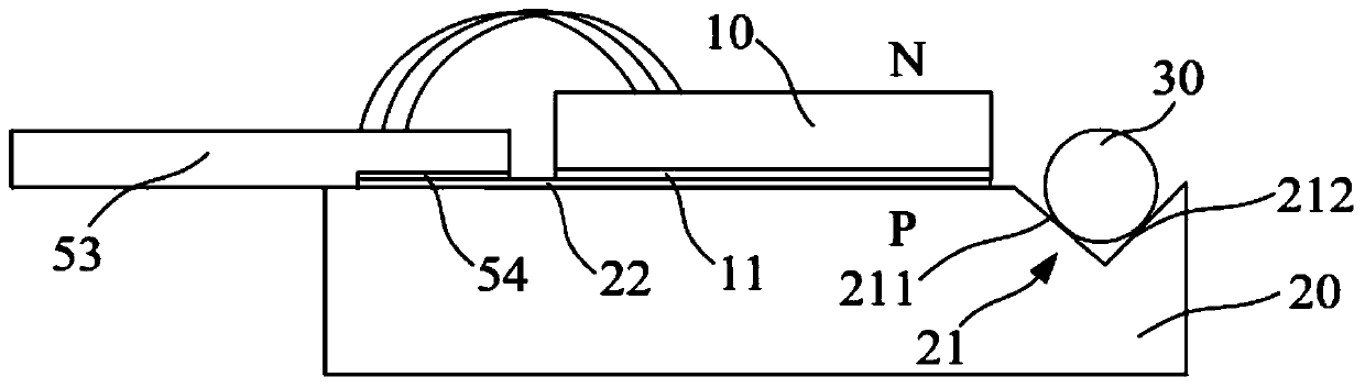
[0028] According to an embodiment of the present invention, the laser emitting device of the lidar mainly includes a laser source, a heat sink component, an optical fiber, a semiconductor refrigerator, an emitting circuit board, and a chassis. Wherein, the laser source is placed upside down on the heat sink part, the opt...


PUM


Abstract

The invention provides a laser emitting device for a laser radar. The laser emitting device comprises a laser source used for emitting a laser beam and including an N pole and a P pole; and a heat sink component used for dissipating the heat of the laser source. The laser source is disposed on the heat sink component, and the P pole of the laser source is soldered to the heat sink component. The invention also provides a laser radar comprising a rotor, wherein the laser emitting device is disposed in an emitting bin of the rotor. According to the laser emitting device of the invention, the laser source is inverted on the heat sink component, and the heat sink component dissipates a large amount of heat generated by the laser source during operation, thereby effectively solving the problemthe laser source generates a large amount of heat and the heat is difficult to be exported, so that the laser source can be prevented from being damaged by excessively high temperature.

Description

technical field [0001] The invention relates to the technical field of laser radar, in particular to a laser emitting device of the laser radar and a laser radar including the laser emitting device. Background technique [0002] As an important part of the intelligent vehicle environment perception hardware system, Lidar (LIDAR) undertakes important tasks such as roadside detection, obstacle recognition, and real-time localization and mapping (SLAM) in automatic driving. The LIDAR system consists of a laser emitting system and a receiving system. The laser transmitter system generates and emits light pulses, hits the object and reflects back, and is finally received by the receiver. The receiver accurately measures the travel time of the light pulse from when it is emitted to when it is reflected back. Because light pulses travel at the speed of light, the receiver will always receive the previous reflected pulse before the next one is sent. Given that the speed of light ...

Claims


Application Information

Patent Timeline
Patent Type & Authority Applications(China)
IPC IPC(8): G01S7/484G01S17/93
Inventor 陈杰向少卿
Owner HESAI TECH CO LTD
Why Eureka
Try Eureka