Energy storage charging system

Pending Publication Date: 2019-06-21
SHENZHEN YINGFEIYUAN TECH CO LTD
View PDF0 Cites 5 Cited by
  • Summary
  • Abstract
  • Description
  • Claims
  • Application Information

AI Technical Summary

Problems solved by technology

[0005] The technical problem to be solved by the present invention is an energy storage and charging system. The energy storage device and the DC bus are isolated by a high-frequency transformer. many deficiencies

Method used


Image

  • Energy storage charging system
  • Energy storage charging system
  • Energy storage charging system

Examples


Embodiment approach 1

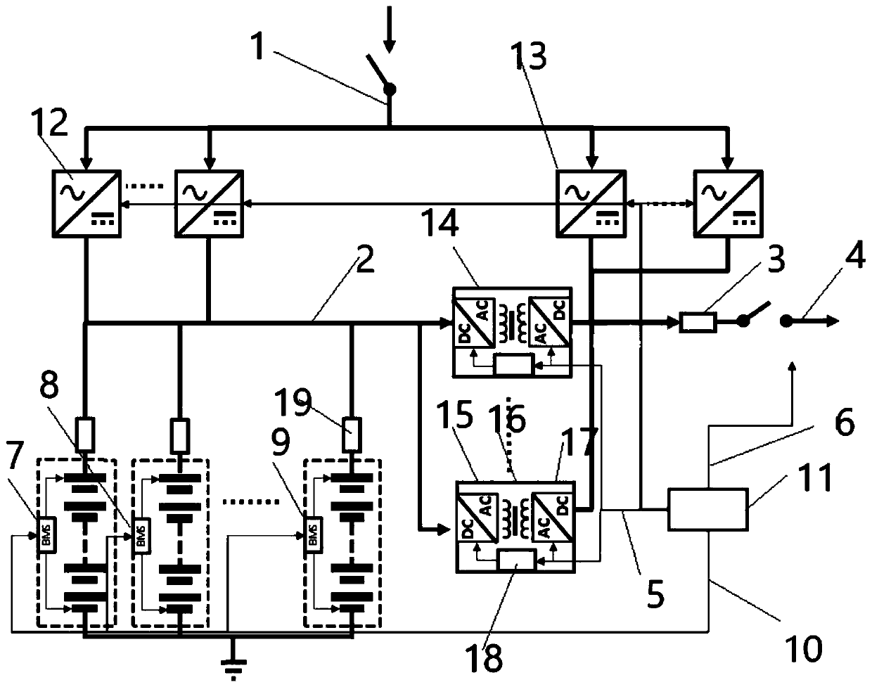
[0047] as attached figure 2 As shown, a high-frequency isolation conversion energy storage charging system includes a high-frequency isolation conversion DC / DC conversion device 14, an energy storage DC bus 2, an energy storage battery pack 7 / 8 / 9, and a bidirectional charging AC / DC device 12 , a bidirectional load power supply AC / DC device 13 , a load DC bus 3 , an electric vehicle or other load interface 4 , and a system master 11 .

[0048] The high-frequency isolation conversion energy storage system includes multiple sets of battery packs, and the energy storage DC bus connected to the batteries. The energy storage charging ACDC conversion device is connected to the AC power grid and the energy storage DC bus.

[0049] The energy of multiple groups of batteries supplies power to the load through DC / DC conversion, and at the same time, the grid charges the battery groups through the AC / DC conversion device. The battery pack can also reversely feed the grid through bidire...

Embodiment approach 2

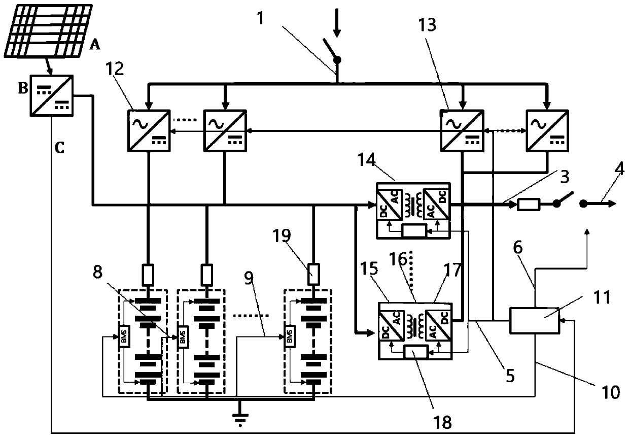
[0053] as attached image 3 As shown, the photovoltaic array A is connected to the energy storage DC bus through the MPPT maximum power tracking conversion device B. At the same time, the high-frequency isolation conversion device connects multiple battery packs to the load DC bus, and the load DC bus is connected to electric vehicles or other types of loads. Charging port for charging electric vehicles or other types of loads.

[0054] The above embodiment is a photovoltaic energy storage charging system. The electric energy can be supplemented by the photovoltaic array, and the energy storage DC bus is powered through the maximum power tracking, and then the load equipment is supplied with power through the load DC bus. The excess electric energy is stored in the energy storage system. Battery. When there is no solar energy or the solar energy is not enough, the alternating current or the discharge of the battery pack is used to provide electric energy to the load bus.


PUM


Abstract

The invention discloses an energy storage charging system, which comprises an AC / DC converter and a DC / DC converter, wherein the high-frequency isolation conversion AC / DC converter takes power from power grid to supply power to a load, and the high-frequency isolation conversion DC / DC converter discharges power from battery to supply power to the load. The energy storage charging system is chargedby converting the charging ACDC into direct current electric energy, and meanwhile, the high-frequency isolated DCDC conversion device can discharge electricity to the load power supply bus, and simultaneously, the ACDC connected with the alternating current converts the alternating current electric energy into direct current electric energy to the load power supply bus to supply power to the load. The charging ACDC is isolated through the high-frequency isolation transformer, and the electric energy passing through a transformer is adjusted, so that the charging voltage and current of the direct-current bus to an energy storage device are adjusted; and a power supply DCDC is isolated through the high-frequency isolation transformer, the electric energy passing through the transformer isadjusted, and the power supply voltage and current of the load power supply bus are adjusted, so that the purpose of charging an electric vehicle or other types of loads is achieved.

Description

technical field [0001] The invention relates to a charging system, in particular to an energy storage charging system. Background technique [0002] Generally, electric vehicles or other types of load charging systems draw power from the AC grid, but due to the limitation of the AC grid in terms of power supply, especially the limited capacity of a single box-type transformer, it is impossible to connect to a charging system that exceeds its capacity. At the same time, there are differences in the electricity cost of the AC power grid at different times, and the charging of electric vehicles or other types of loads is a random electricity consumption, so there are cases where peak electricity charges are used, or full power charging cannot be performed. [0003] At the same time, in the energy storage system currently in use, when the energy storage device is connected to the DC bus, there is a short-circuit protection problem. That is to say, when the DC bus is short-circu...

Claims


Application Information

Patent Timeline
Patent Type & Authority Applications(China)
IPC IPC(8): H02J7/00H02J7/02H02J7/35B60L53/00
CPCY02T10/92B60L3/0069H02J7/0013H02J2207/20H02J1/102H02J2310/48B60L53/20H02J7/007H02J7/02H02J7/35
Inventor 王渭渭朱春辉岳兴
Owner SHENZHEN YINGFEIYUAN TECH CO LTD
Why Eureka
Try Eureka