
Multifunctional medical pendulum saw

A multifunctional, swinging head technology, applied in the field of medical equipment, can solve the problems of unfavorable secondary disinfection treatment, access to the inside of the tool, and corrosion of internal parts, and achieve the effects of simple structure, reduced diameter, and reduced weight

Active Publication Date: 2019-06-28
上海博进医疗器械有限公司
View PDF5 Cites 3 Cited by
  • Summary
  • Abstract
  • Description
  • Claims
  • Application Information

AI Technical Summary

Problems solved by technology

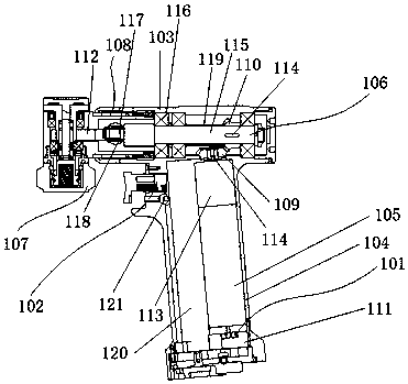
[0002] In orthopedic surgery, it is often necessary to use a saw blade to remove the damaged bone tissue of the patient. During the cutting process, in order to avoid excessive bleeding of the patient, the smaller the wound, the better. High-speed oscillating cutting within the stroke, due to the small swing and high swing frequency, the oscillating saw can only remove bone tissue without hurting muscles, soft tissues and nerve tissues. However, the medical oscillating saw in the prior art, The motor is placed horizontally, parallel to the swing shaft and the split fork, and the output torque of the swing saw is related to the size of the motor. This results in a large output torque, which requires a large diameter motor, but the operator needs to be miniaturized, which creates a contradiction , In addition, because the pendulum saws currently on the market do not have an effective sealing structure, the blood during use will enter the inside of the tool, causing corrosion of internal parts, which is also not conducive to secondary disinfection treatment

Method used


Image

  • Multifunctional medical pendulum saw
  • Multifunctional medical pendulum saw
  • Multifunctional medical pendulum saw

Examples


Embodiment Construction

[0027] In order to make the technical means, creative features, objectives and effects of the invention easy to understand, the present invention will be further elaborated below in conjunction with specific illustrations.

[0028] The first embodiment of the present invention is to provide a multi-functional medical oscillating saw. The purpose is to reduce the diameter of the output shaft of the motor by placing the motor vertically in the handle, and effectively solve the contradiction between small volume and high output torque; an oil seal is used as the dynamic Sealing structure, adding an effective sealing structure, can block blood and water from entering the inside of the swing saw body, will not cause pollution inside the swing saw body, and can effectively prolong the service life of the tool; the structure is simple, the weight of the moving parts is reduced, and the reactive power is reduced as much as possible Loss, thereby reducing the operating current and prolo...


PUM


Abstract

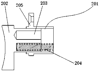
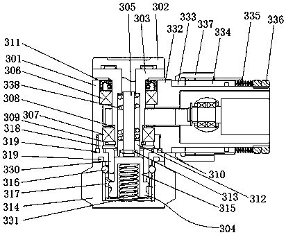
The invention discloses a multifunctional medical pendulum saw. The multifunctional medical pendulum saw includes a control device, a casing, a handle, a motor, a transmission device and a pendulum head. One end of the casing is provided with a rotation device connected with the pendulum head, the casing is fixedly connected with the top of the handle, the control device is connected with the handle, the transmission device is arranged in the casing, the motor is arranged in the handle, the top of the motor is provided with a gear set connected with the transmission device, the motor is electrically connected with the control device, and the end, away from the gear set, of the transmission device is provided with a shifting fork connected with the pendulum head; the pendulum head includesa pendulum includes a pendulum shell, a pressure plate, a cutter frame and a rotary knob, the pendulum shell is connected with the rotation device, the rotary knob is arranged on the bottom of the pendulum shell, the cutter frame is arranged at the top of the pendulum shell, the bottom of the cutter frame stretches into the pendulum shell partially, the cutter frame is connected with the shiftingfork, the pressure plate is arranged at the top of the cutter frame, the bottom of the pressure plate is provided with a connection rod running through the cutter frame and connected with the rotary knob, the connection rod is sleeved with a return spring, and the control device controls and is connected with the motor.

Description

technical field [0001] The invention relates to the technical field of medical instruments, in particular to a multifunctional medical pendulum saw. Background technique [0002] In orthopedic surgery, it is often necessary to use a saw blade to remove the damaged bone tissue of the patient. During the cutting process, in order to avoid excessive bleeding of the patient, the smaller the wound, the better. High-speed oscillating cutting within the stroke, due to the small swing and high swing frequency, the oscillating saw can only remove bone tissue without hurting muscles, soft tissues and nerve tissues. However, the medical oscillating saw in the prior art, The motor is placed horizontally, parallel to the swing shaft and the split fork, and the output torque of the swing saw is related to the size of the motor. This results in a large output torque, which requires a large diameter motor, but the operator needs to be miniaturized, which creates a contradiction , In addi...

Claims


Application Information

Patent Timeline
IPC IPC(8): A61B17/14
Inventor 曲人晶王熙迥王浩
Owner 上海博进医疗器械有限公司
Learn More