Convection device and convection method

A convection channel and substrate installation technology, which is applied in manufacturing auxiliary devices, processing environment adjustment, etc., can solve the problem of high cost, achieve the effects of reducing air volume requirements, facilitating laser focusing, and reducing the consumption of the whole machine

Active Publication Date: 2022-01-07
HANS LASER TECH IND GRP CO LTD
View PDF5 Cites 0 Cited by
  • Summary
  • Abstract
  • Description
  • Claims
  • Application Information

AI Technical Summary

Problems solved by technology

[0005] The technical problem to be solved by the present invention is to provide a convection device and a convection method in view of the high cost technical defect caused by the convection of the inert gas on the surface of the existing printing area.

Method used


Image

  • Convection device and convection method
  • Convection device and convection method
  • Convection device and convection method

Examples


Embodiment Construction

[0034] In order to make the technical problems, technical solutions and beneficial effects solved by the present invention clearer, the present invention will be further described in detail below in conjunction with the accompanying drawings and embodiments. It should be understood that the specific embodiments described here are only used to explain the present invention, not to limit the present invention.

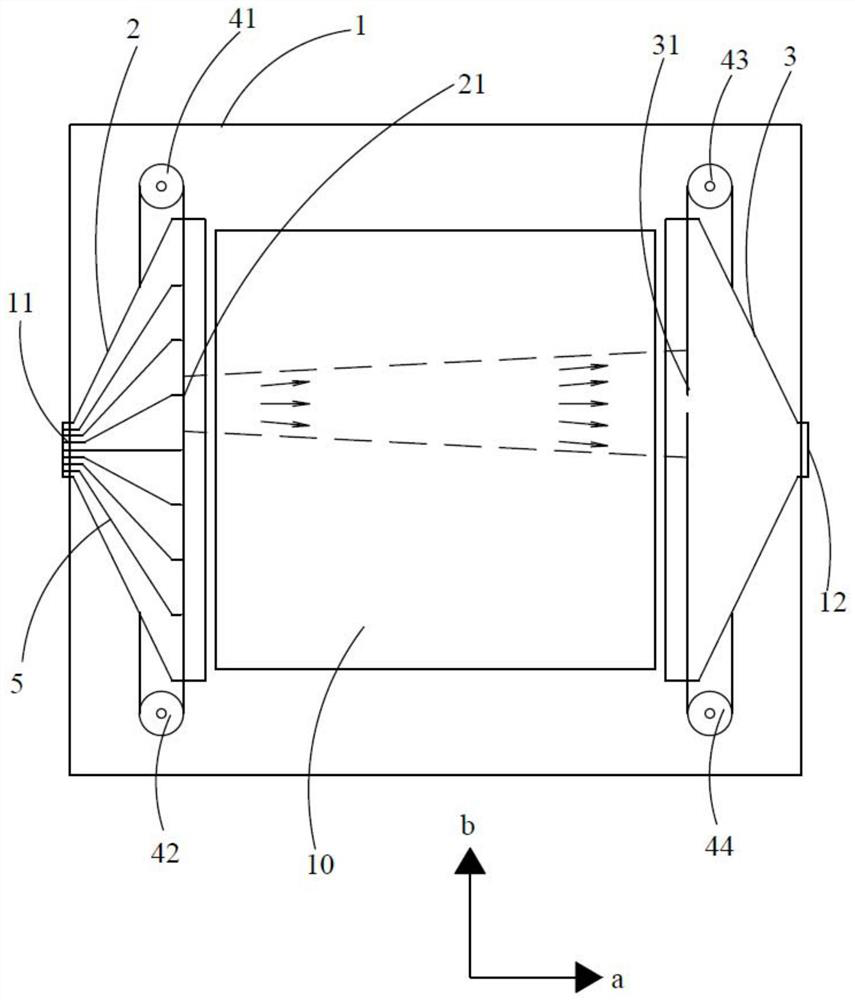
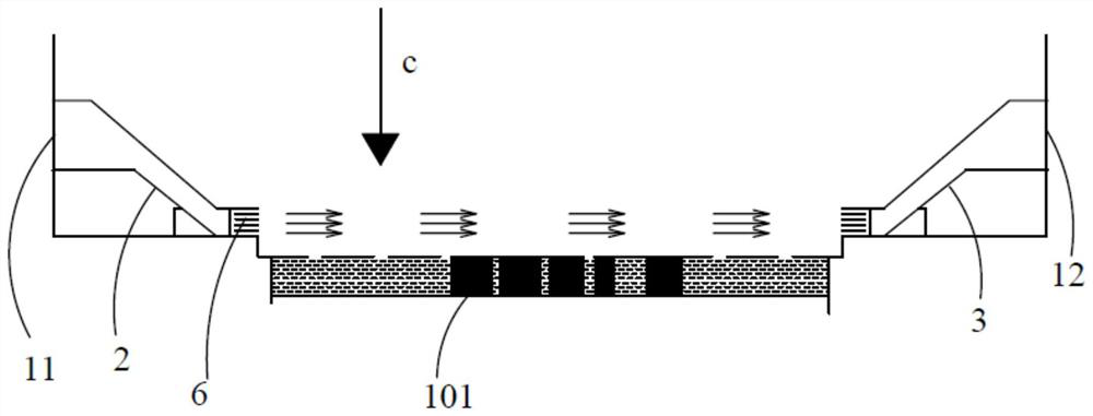
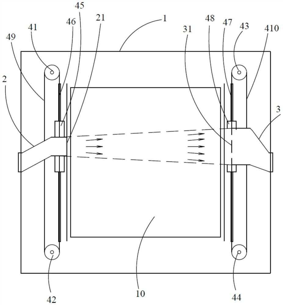
[0035] An embodiment of the present invention provides a convection device, including a mounting substrate 1, a first guide 2, a second guide 3 and a drive mechanism, the mounting substrate 1 is located above the printing area 10, the first guide 2 and the second guide 3 are all arranged on the installation substrate 1, one end of the first guide 2 communicates with the air source, the other end of the first guide 2 is formed with a first gap 21, one end of the second guide 3 communicates with the outside world, and the second guide The other end of the member 3 is forme...


PUM


Abstract

The invention belongs to the technical field of additive manufacturing preparation, and in particular relates to a convection device and a convection method. In the convection device, since the other end of the first guide member is formed with a first notch, and the other end of the second guide member is formed with a second notch, the first notch is opposite to the second notch to form a convection channel, and the first guide Both the component and the second guiding component are connected on the installation substrate, and the installation substrate is located above the printing area. In this way, when the printing on the printing area reaches a certain area, the driving member drives the first guide member and the second guide member to move to correspond to the area being printed, so that the first notch and the second guide member on the first guide member The second gap corresponds to the area being printed, so that there is always a convective wind blowing over the area being printed, so that the sputtering and smoke can be well taken away, and the laser focus is convenient. In addition, the convection channels always correspond to the area being printed, which greatly reduces air volume requirements and reduces machine costs.

Description

technical field [0001] The invention belongs to the technical field of additive manufacturing preparation, and in particular relates to a convection device and a convection method. Background technique [0002] Factors such as the building platform of the additive manufacturing equipment, the temperature of the molding protection chamber, the oxygen concentration of the protection chamber, and the speed of the inert gas flowing over the powder surface will affect the process conversion and the formation of part defects. [0003] When printing, the laser focuses on the surface of the metal powder and passes quickly across it. At a certain moment, splashes and smoke will be generated near the molten pool, which will affect the laser focusing effect at the next moment, causing a large change in the temperature of the focus point. In addition, the sputtered particles are splashed on the surface of the processing area and mixed in the powder. These particles melt at higher tempe...

Claims


Application Information

Patent Timeline
Patent Type & Authority Patents(China)
IPC IPC(8): B29C64/364B22F12/70
Inventor 王先礼喻鹏袁剑吕启涛高云峰
Owner HANS LASER TECH IND GRP CO LTD
Why Eureka
Try Eureka